
Welcome to my “Balsa RC Model Builders Page.” Every project featured here is one of my hand built balsa RC aircraft. I've been building RC models for more than 37 years — starting with kits, then gradually shifting to scratch building. In fact, all but one of my last twenty aircraft were built entirely from scratch.
Working with balsa, plywood, and a set of 2–D plans has always fascinated me. There's something special about watching those flat drawings transform into a fully functional 3-D flying model. Through the build descriptions I share here, my goal is to help other RC modelers avoid some of the pitfalls and mistakes I've encountered along the way (and still run into from time to time).
If you ever have questions during your own scratch-build projects, I'm always happy to help however I can.
If you are serious about trying to build your own Balsa RC model aircraft, you should look at the "Magnetic Build Board" section I have on this page. It contains the link to "Airfield Models". Airfield Models has really great information on building Balsa models. I also provided you with the link to "RCPlanes.Online". RCPlane.Online has a great CG calculator along with various other calculation programs you might need for building your own RC models.
"Aerofred.com" and "Outerzone.co.uk" are two of my favorite web sites to obtain RC model airplane plans for new scratch builds. Additionally, they like to post images of Builder's models, and both sites have posted my RC model images and build descriptions under the heading of the associated aircraft model. Other good sources for plans are: "Hip Pocket Aeronautics Builders' Plan Gallery", "Vintage & Old-Timer RCM Free Plans", "James Hatton Blog Free Plans and Articles", "Hlsat Blog RCModeler Free Plans and Articles", and "Don Dewey Memorial RCM Plans Collection."
To aid in getting the plans you download to a set of full-size plans, I highly recommend you take the time to view a great 2-part video series produced by Mark Robinson titled "Download & Print Plans - Balsa Model Airplane Building". He also has an excellent 3-part video titled "Building from Plans:". Another good 3-part video series on finding, reading, and using plans to build an RC model is available from Joyplanes @: Plans for RC Aircraft Masterclass. I also recommend your use PDF X to view/edit and print your RC model plans.
NOTE - You can view all images using a “Spotlight Box” by simply clicking on any image.
Click on any link below to jump to that Balsa RC Model Section
Project on Hold - Douglas A-26 Invader
Updated - USAF OA-1K Skyraider II
Andy Clancy's Stagger Bee
Miss Vintage
AMTN Beechcraft Starship
Andy Clancy's Speedy Bee
1929 Velie Monocoupe
Some Old School Build Pictures
S.T.O.L. Pigeon
Junior Telemaster
PDF Instruction's for Larry's Big Table
Cloud Dancer
Bokkie
150% SIG Wonder
Big Bird II
Double Trouble 40
Magnetic Build Board & 1935 Aeronca C-3
Ed Kazmirski Simla
1911 Voisin Canard
Big Double Trouble & X-20
A Blended Wing Body (BWB) Concept
Douglas A-26 Invader Scratch Build
Having completed my scratch build of a 1/15th Semi-Scale USAF OA-1K Skyraider II, I wanted to try and see what I could come up with in the way of a twin engine post WW-II ground attack aircraft to add to my military collection. In doing research for my May 2026 “Build of the Month” Edition, I ended up selecting the Douglas A-26 Invader. After looking through and reading all the material for the BOTM Edition, I decided I would set off to try and develop a set of plans for a 1/15th Semi-Scale Douglas A-26 Invader, and then attempt a balsa scratch build as my next RC model project.
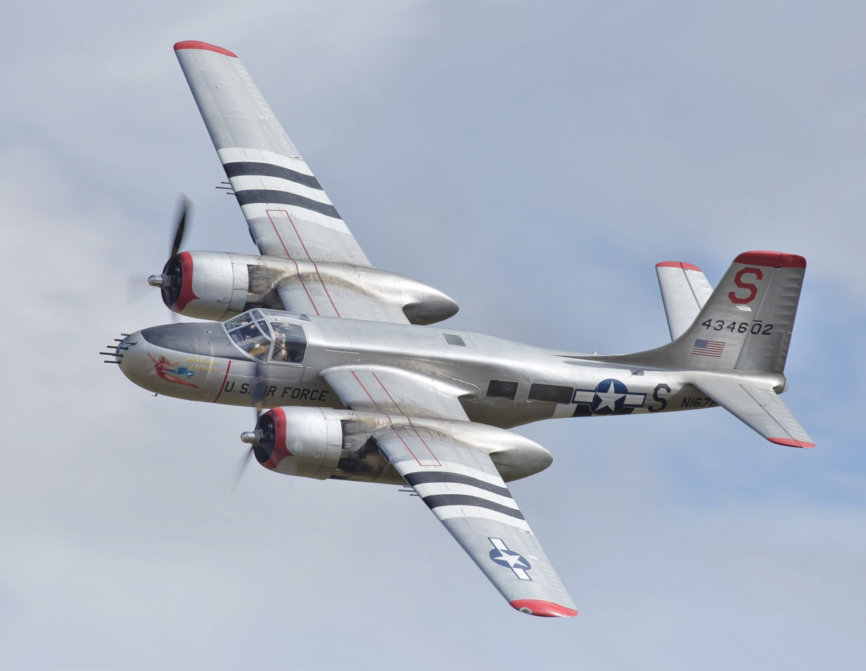
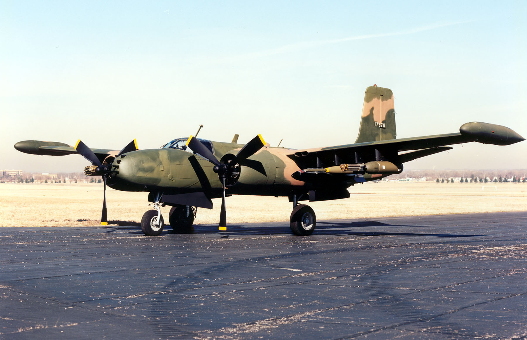
Source of Images: Wikipedia.
This updated posting is as of 9 May 2026, and for those who have not been following my regular webpage updates, you can read my Latest Version of my 1/15th Semi-Scale Douglas A-26 Invader Build Description to see everything I have been through up to this point.
1/15th Semi-Scale A-26 Invader Plans Development Re-Cap
Let's do a quick recap of what has been accomplished to date in the development of some 2D CAD plans for my 1/15th Semi-Scale A-26 Invader. Starting with a set of 3-view drawings of actual A-26 aircraft, I first took measurements and profiles for each major component (fuselage, wings, tail feathers, nacelles, etc.). Using these I reduced the actual measurements down to a 1/15th scale and developed a starting point for the various plans needed to scratch build my RC model.
Using my experience in modification of many other RC model plans for earlier scratch builds, together with a review of several other A-26 RC model plans, I started to lay out the various 2D plans for each of the A-26 Invader major components. I made initial assumptions of the overall RC model weight to establish what I would need for an electric power system and selected what I felt were the best locations for each of the system components (LiPos, ESCs, servos, etc.).
I started my scratch build plans development with the tail feathers, and once those were finished I moved next to the fuselage. Here I debated using full balsa sheets versus narrow balsa strips to cover the outside of the fuselage formers, and my initial design used the full sheets approach. This then drove using fuselage formers that are basically rectangles with rounded corners which is not a “true representation” of the actual A-26 fuselage shape, hence a “semi-scale” model design. Another debate was to use retractable gear versus the standard bent music wire landing gear arrangement. With my 1/15th Scale A-26 design being fairly small for a twin engine model, I elected not trying to squeeze retracts into the motor nacelles since they would be filled with the LiPo/ESCs.
Due to their interdependencies, in order to finish the fuselage plans I needed to work up my initial plans for the wing. The ailerons in my RC model are slightly larger than those on the actual A-26, but this adds some roll control to the model. I had considered putting flaps running from wing ribs R5-R7 but elected to not add them to reduce the model's weight, and I need that area in the wing to add the weapons stations pylon attachment hardware. With the wing profile and dihedral established I was able to finalize the fuselage plan sheet and developed a fuselage templates plan sheet.
Finally, I developed the plan for the motor nacelles. This part of my model design was the hardest for me to draw up. Most of the other A-26 RC model plans I reviewed used nacelles based on a rectangular shape with sheeted sides, top, and bottom. I wanted to try and capture the real A-26 nacelles using a round shaped nacelle design that is covered using narrow 1/16” or 3/32” balsa strips to better fit the wing profiles. In order to understand the interface between the nacelle and wing profile I used a 2D front view of the wing/nacelle and developed a 3D model of the various nacelle parts. Using these I not only completed the nacelle plan sheet but also designed 3D models to support 3D printing of the nacelle cowls, tail cones, dummy Wasp engines, and some MLG strut covers/straps.
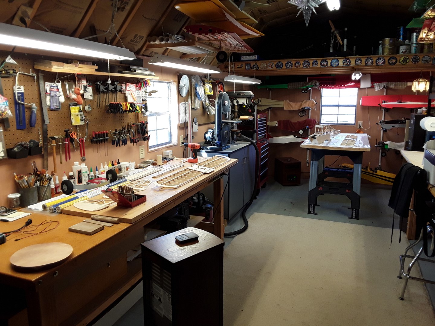
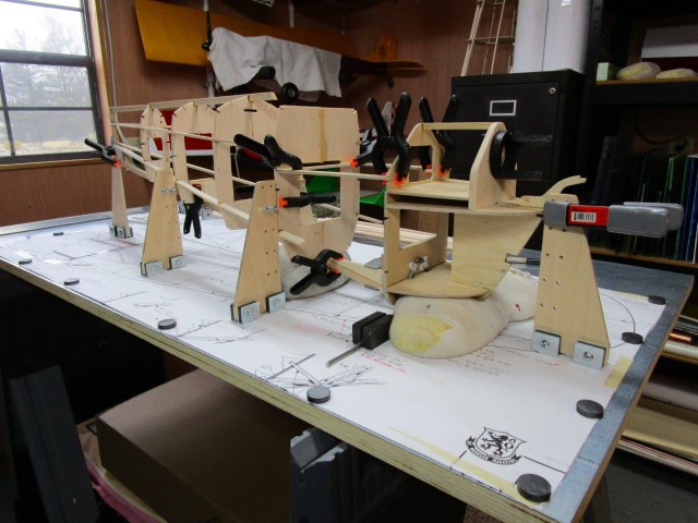
With my primary building table currently occupied with a Hot Air Balloons Stained Glass Panel assembly, starting the A-26 scratch build will have to be placed on hold until that glass panel is finished. But there are other 3D models that need to be developed for the A-26, such as gun turrets, nose guns, antennas, cockpit canopy, and maybe even the rear gunner canopy. The progress on these can be followed on my “3D Modeling & Printing” Page.
Stay tuned for more to come!!!
Latest Version of my 1/15th Semi-Scale Douglas A-26 Invader Build Description.
See All Images Taken During my A-26 Invader Scratch Build.
See All 3D Modeling Efforts for my A-26 Invader Scratch Build.
An Awesome A-26B Invader RC Scale Plane Scratch Build Webpage.
USAF OA-1K Skyraider II Scratch Build
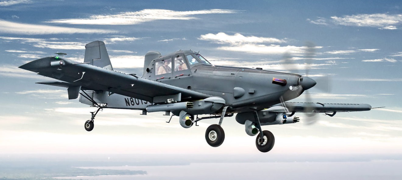
Having served 24 years in the US Air Force, I tend to keep track of new USAF developments, especially when it comes to new aircraft. One that caught my attention was the new OA-1K Skyraider II. The Air Force Special Operations Command (AFSOC) marked a new chapter with its latest aircraft on 3 April 2025 when the first Skyraider II fully modified for military use arrived at Hurlburt Field, Fl. Additional OA-1K aircraft will flow from the L3Harris production line to Will Rogers Air National Guard Base, Ok. where the Skyraider II formal training unit is located.
Check out a nice video showing many close-up views of the OA-1K at Hurlburt Field, FL @: Introducing the new OA-1K Skyraider Il Special Operations Aircraft.
For a Semi-Scale scratch build of the OA-1K Skyraider II, my starting point was the Airtractor AT-802. I was able to find a set of plans from the AeroFred Airtractor AT-802 Webpage for a 46.5″ wingspan (approx. 1/15th scale) electric-powered model designed by Chalepmpol Hamaunsa.
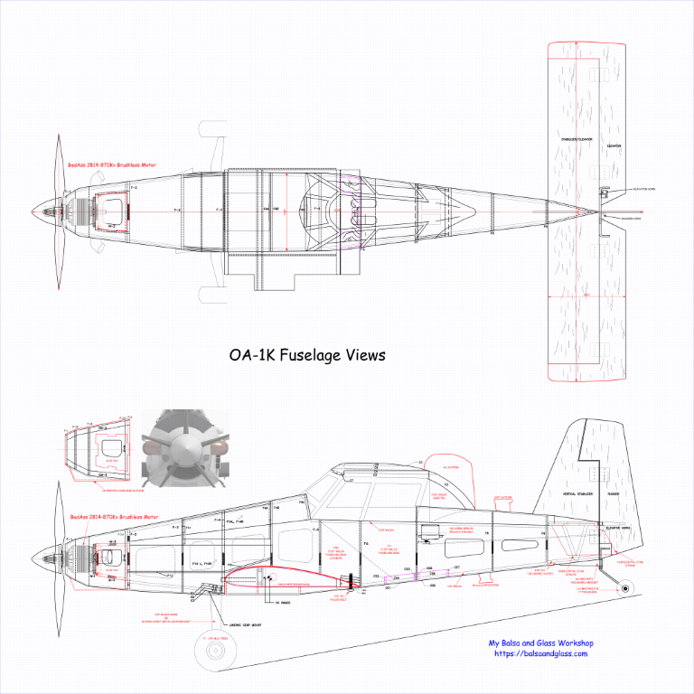
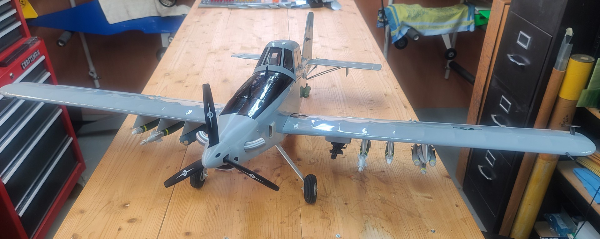
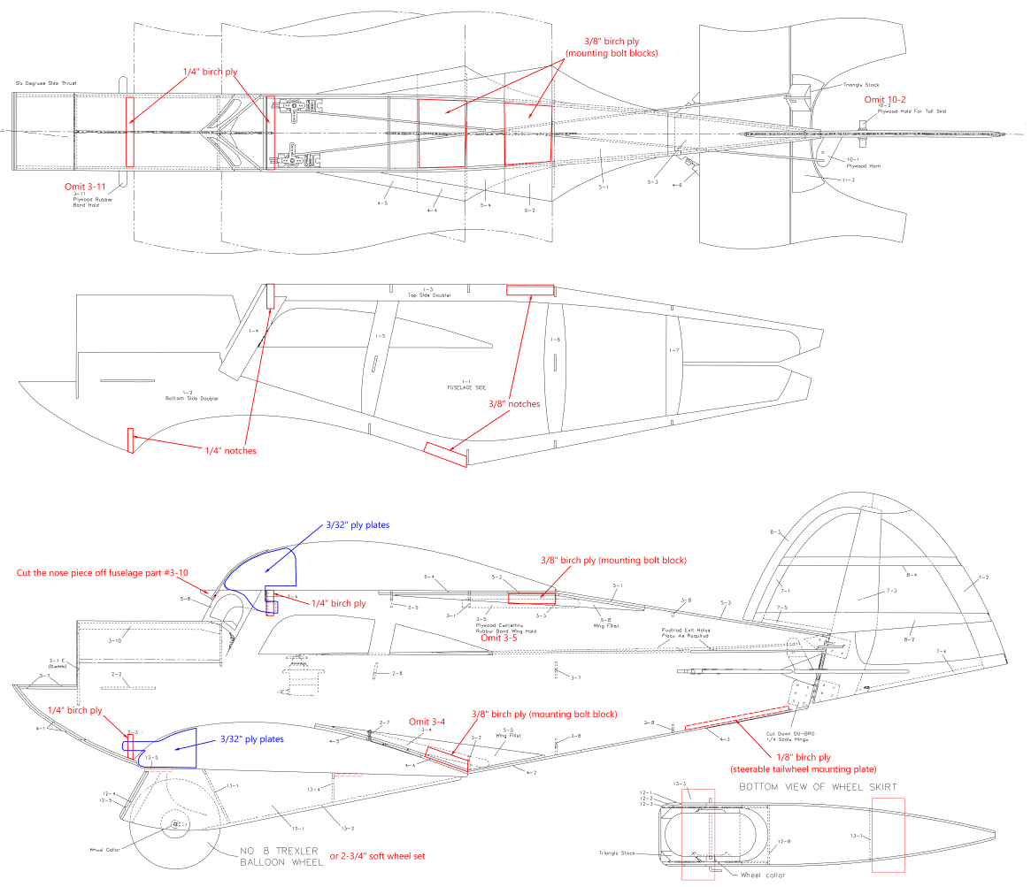
Using these plans I made many modifications that better represent the actual design of the OA-1K. You can see some of these modification in the second image to the right. A detailed explanation of all the various model plan changes are captured in my build description and my OA-1K plans. To power this little beast I selected a BadAss Power System that puts out 680 watts and is comprised of the following components — Motor: BadAss 2814-980Kv Brushless; ESC: BadAss Rebel V2 Series Brushless ESC, 50A; Battery: BadAss 45C 2,600mah 4S LiPo; Prop: MAS 9x7 3-Blade Prop. This will provide a power ratio of approx. 1:1 for my Skyraider II. I purchased my power system from Innov8tive Designs.
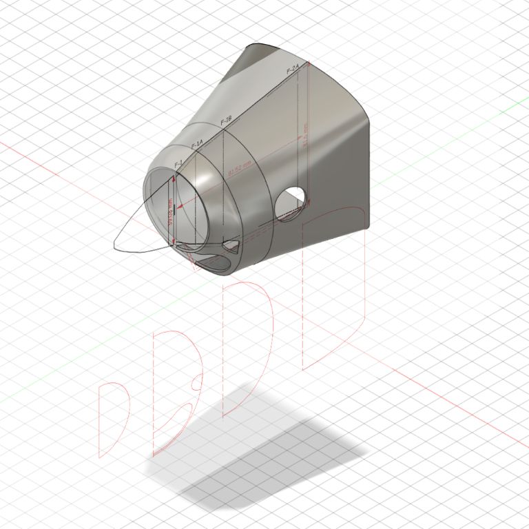
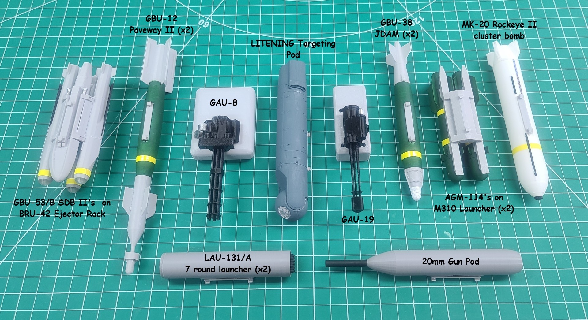
The major difference for this scratch build from my other builds was the introduction of 3D modeling and printing. For my OA-1K model I purchased a Creality Ender-3 V3 3D printer, and learned how to build 3D models (like that in the third image to the right) using Autodesk Fusion 360. In addition to the nose cone, the prop spinner, communication system antennas, horizontal stab strake's, pilot & mission payload operator busts, various cooling air scoops/vents/grills, wing weapon hardpoint rails, pylons, and all “External Stores” were also 3D printed.
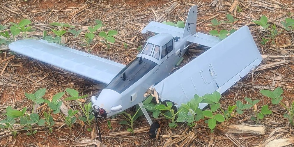
Well, after several months of having my OA-1K sitting on the rack in my workshop, I finally took her to the flying field for her first flight. The wind was blowing more than I would have liked, but it was straight down the runway, so I decided to go for it. I throttled her up slowly and made a good climb to altitude, made my first circle of the flying field with her handling just fine, then she went wild and I lost all control of her. Results of my first flight attempt can be seen in the bottom image to the right. Fortunately, the damage was limited to the wing, prop, spinner, and nose cone. When I opened the LiPo bay cover I found the LiPo pack XT60 connector was pulled apart. Not real sure how this occurred since nothing inside the bay had moved, and there was slack in the cable when the LiPo was installed. Post crash inspection found everything still working as expected after the LiPo pack was reconnected.
So, my plan is to build a new wing, 3D print a new spinner and nose cone, run a complete flight system checkout and receiver range check, and then make another attempt at a good first flight. Yet another example of what you must accept in this hobby. Stay Tuned for More to come!!
If you have any questions about this build, please feel free to send me an email @: OA-1K.
OA-1K Skyraider II Build & Rebuild Description.
OA-1K Skyraider II Plans in .PDF format.
OA-1K Skyraider II Plans in .DXF format.
OA-1K Skyraider II 3D Printed Parts in .STL format.
See All Images Taken During my OA-1K Skyraider II Scratch Build.
See All 3D Modeling Efforts for my OA-1K Skyraider II Scratch Build.


Andy Clancy's Stagger Bee
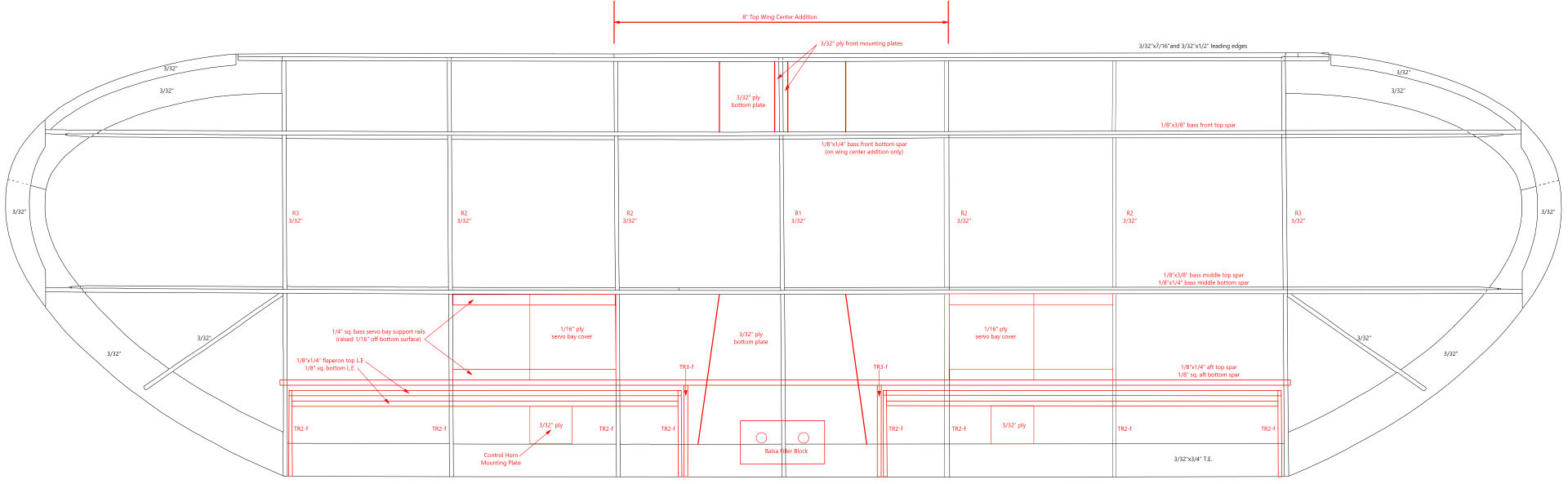
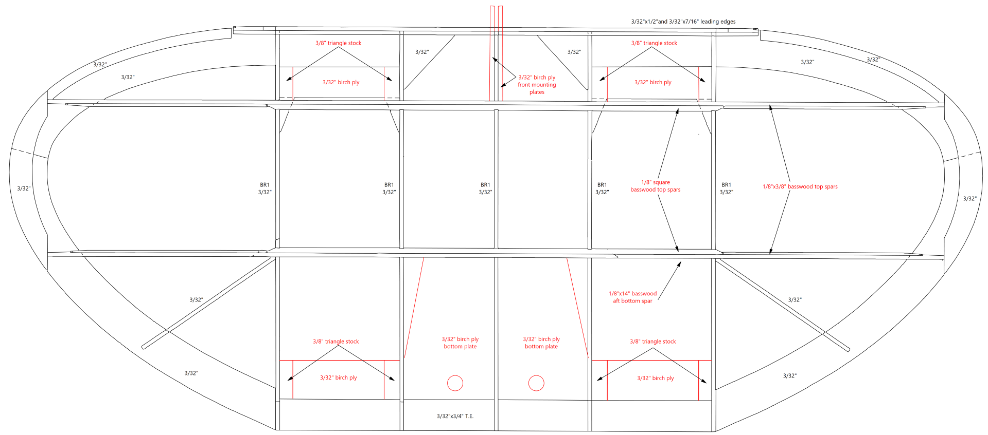
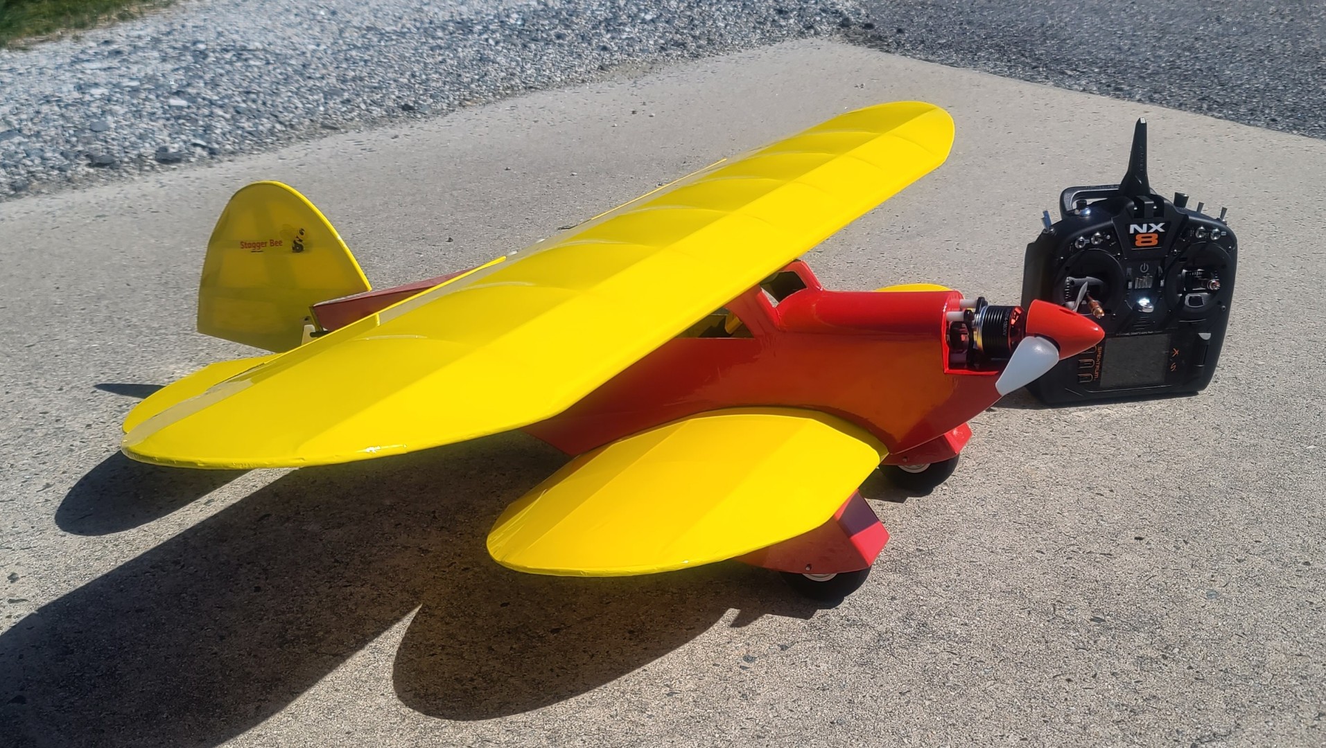
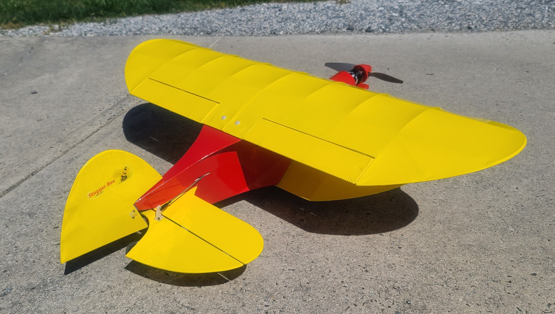
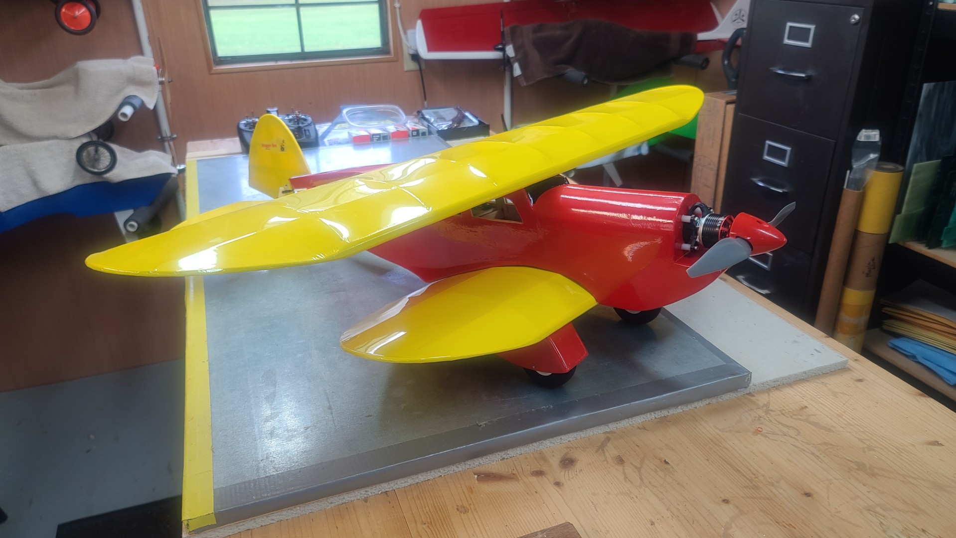
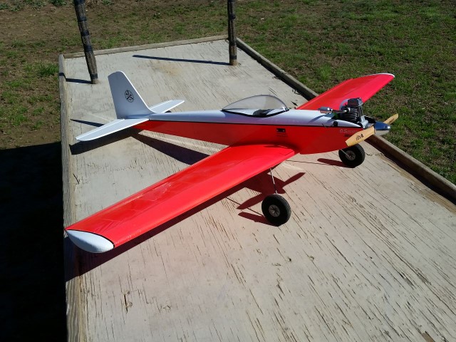
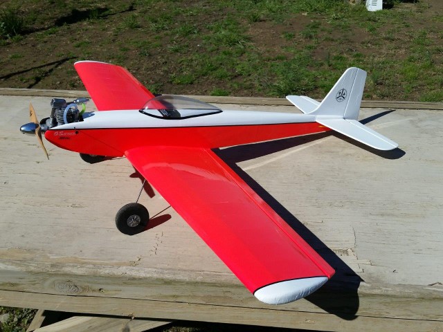
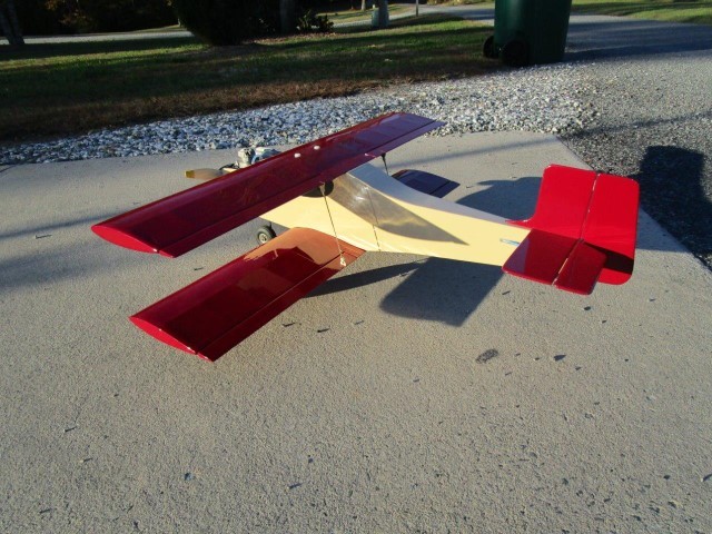
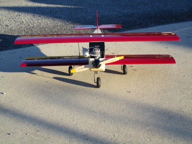
The Stagger Bee captures the special classic grace of a Stagger-wing Beechcraft. Andy's original design is a fun 29″ top and 23.5″ bottom wingspan three channel sport biplane, which is still very much a Bee. You know: Oversized control surfaces, hands-off stability, very low minimum flying speed, and easy aerobatics. The Stagger Bee is just a Bee that is a biplane. It can manage having more power than a Lazy Bee.
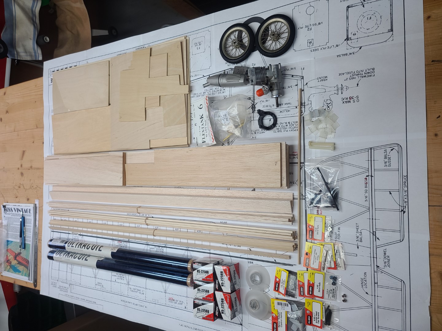
I started my Stagger Bee scratch build using a great set of Andy Clancy Aviation Stagger Bee plans, assembly manual, and an RCM review that you can download from: Aerofred Stagger Bee Webpage, and/or Outerzone Stagger Bee Webpage.
Also, please check out this link to "Andy Clancy Designs"
For my Stagger Bee scratch build, I made several modifications to Andy's plans. These included bolt-on wings and wheel skirts; increased the top wingspan to 37″ and added flaperons; and permanent installation of the tail feathers with a steerable tailwheel. You can see these modification in the first three images to the left. To power this little beauty I used a BadAss Power System that puts out 566 watts, which is equivalent to a .25 two-cycle glow engine. Yes, I built an electric powered model. I know that is hard to believe. This BadAss Power System is comprised of the following components: - Motor: BadAss 2814-1560Kv Brushless; ESC: BadAss Rebel V2 Series Brushless ESC, 60A; Battery: BadAss 45C 3,300mah 3S LiPo; Prop: APC 9x6 E-Series. You can purchase the system from Innov8tive Designs.
If you have any questions about this build, please feel free to send me an email @: Stagger Bee.
Well, one thing I learned a long, long time ago was that if you are going to stay with this hobby, you need to accept the downs that will come sooner or later. Things happen which can result in your model needing a minor repair, or some major repairs, or even a total loss of the model. Such is the case with my Stagger Bee. First flight did NOT go well, and I had to build a new modified fuselage as a result of one wild first flight. On the good side, both of the wings, all tail feathers, and all flight hardware (except the prop) were recoverable and used in my rebuild.
You can read more about the WILD first flight and read about my new Stagger Bee II extender fuselage build (third from bottom left image) in the updated build description below.
Updated Version of My Stagger Bee Build Description.
Stagger Bee Materials and Hardware List.
Full Size Modified Wing Ribs in a PDF file.
See All Images Taken During this Stagger Bee Scratch Build.
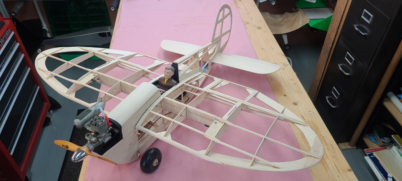
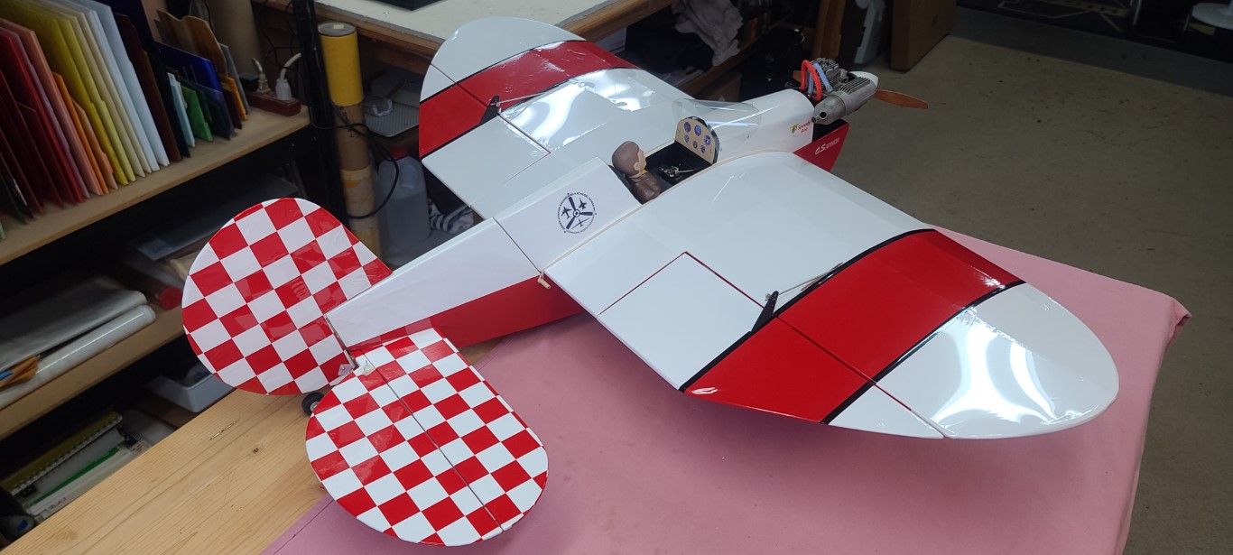
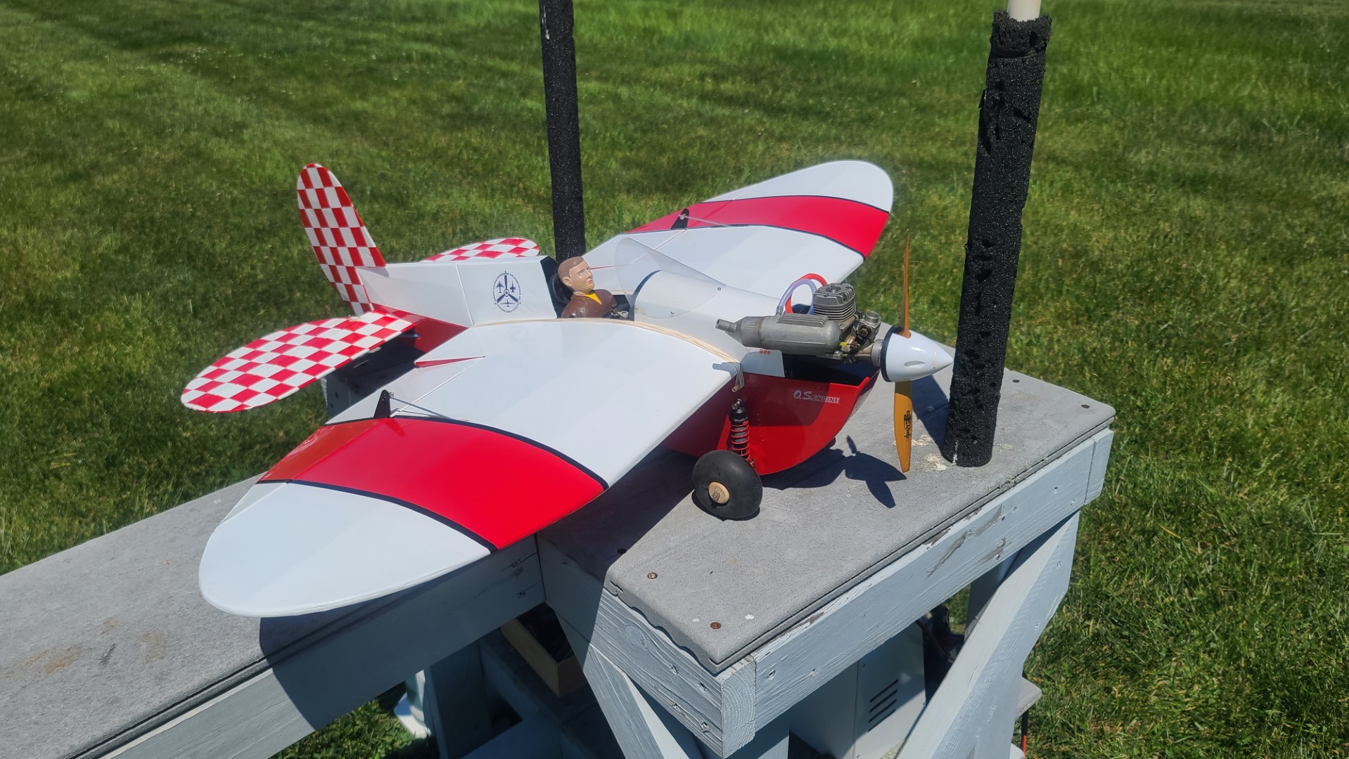
Miss Vintage
While working on the coding for the April 2024 edition of my “Build of the Month” Series, I found the model selection so interesting that I decided to build one for myself. Changes I made to the original design are discussed in my “Miss Vintage Build Description” which you can download using the link provided below.
Miss Vintage is a thoroughly tested and practical machine. Designed around the economical .25 to .35 sized RC engines, it duplicates the looks and slow, deliberate flight characteristics, and realism of an old-timer. It is completely reliable, easy to fly and designed to look complicated and yet be quick and economical to construct.
Wing construction is a snap with a high lift flat bottom airfoil for easy building on a flat surface. Half ribs and diagonal braces are used for strength as well as looks. Ailerons are of the simple and effective strip type, making the choice of three or four channels an easy one for the builder. Little extra effort is required to add ailerons. The fuselage is constructed almost entirely of hardwood. Fuselage sides are cut from 1/8th Lite Ply and are as light as balsa with far greater strength. The open framework is built from 3/16th square spruce which is also very light and strong. The only balsa contained in the fuselage is one bulkhead and the top block. Miss Vintage is a real showstopper guaranteed to attract attention from fellow RC'ers and spectators alike.
Flying capabilities are extremely good. Miss Vintage is capable of many aerobatics including inverted flight and yet is very gentle and easy to fly. Because of the easy take-off and landing characteristics, Miss Vintage could be used as a trainer and first airplane. On the maiden flight of my Miss Vintage, she only needed a couple clicks of down elevator and then flew great. If you have built at least one RC plane and understand basic construction techniques, you can build a Miss Vintage.
If you have any questions about this build, please feel free to send me an email @: Miss Vintage.
My Miss Vintage was built from a great set of Radio Control Modeler (RCM) plans, article, and a review which can be found @: “AeroFred” and/or “Outerzone” and you can download them from:
AeroFred Miss Vintage (plan ID 96793) Webpage.
Outerzone Miss Vintage (oz4746) Webpage.
My Miss Vintage Build Description.
Miss Vintage Materials and Hardware List.
See All Images Taken During the Miss Vintage Scratch Build.


AMTN Beechcraft Starship
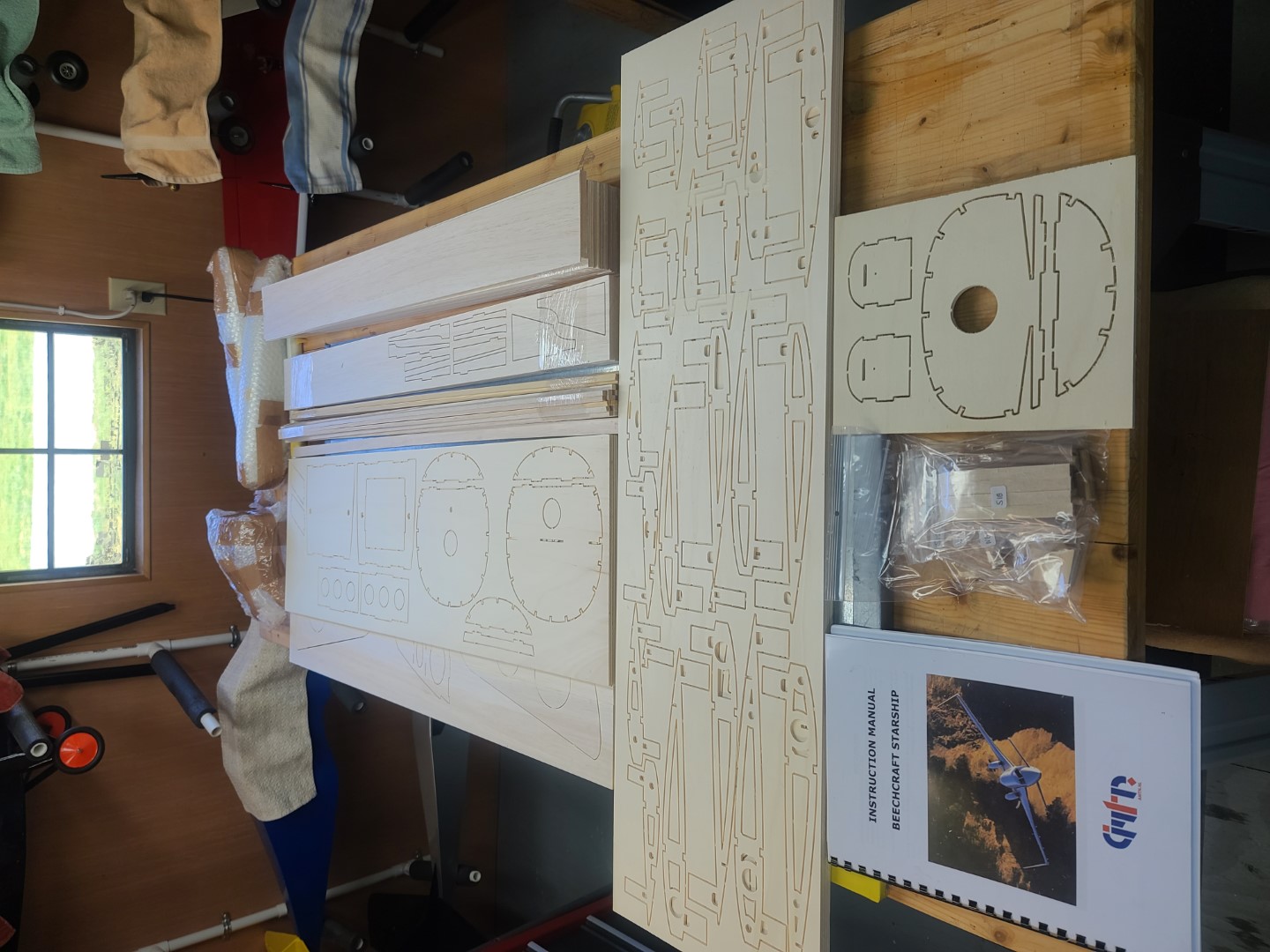
I was contacted by a flying club friend who asked me if I would be interested in building him a new kit he wanted to purchase. Even though this would not be a scratch-build, I was very interested in the kit because I felt I could use the wing and fuselage design to aid me in coming up with a set of plans for the JetZero BWB RC model I discuss further down on this webpage.
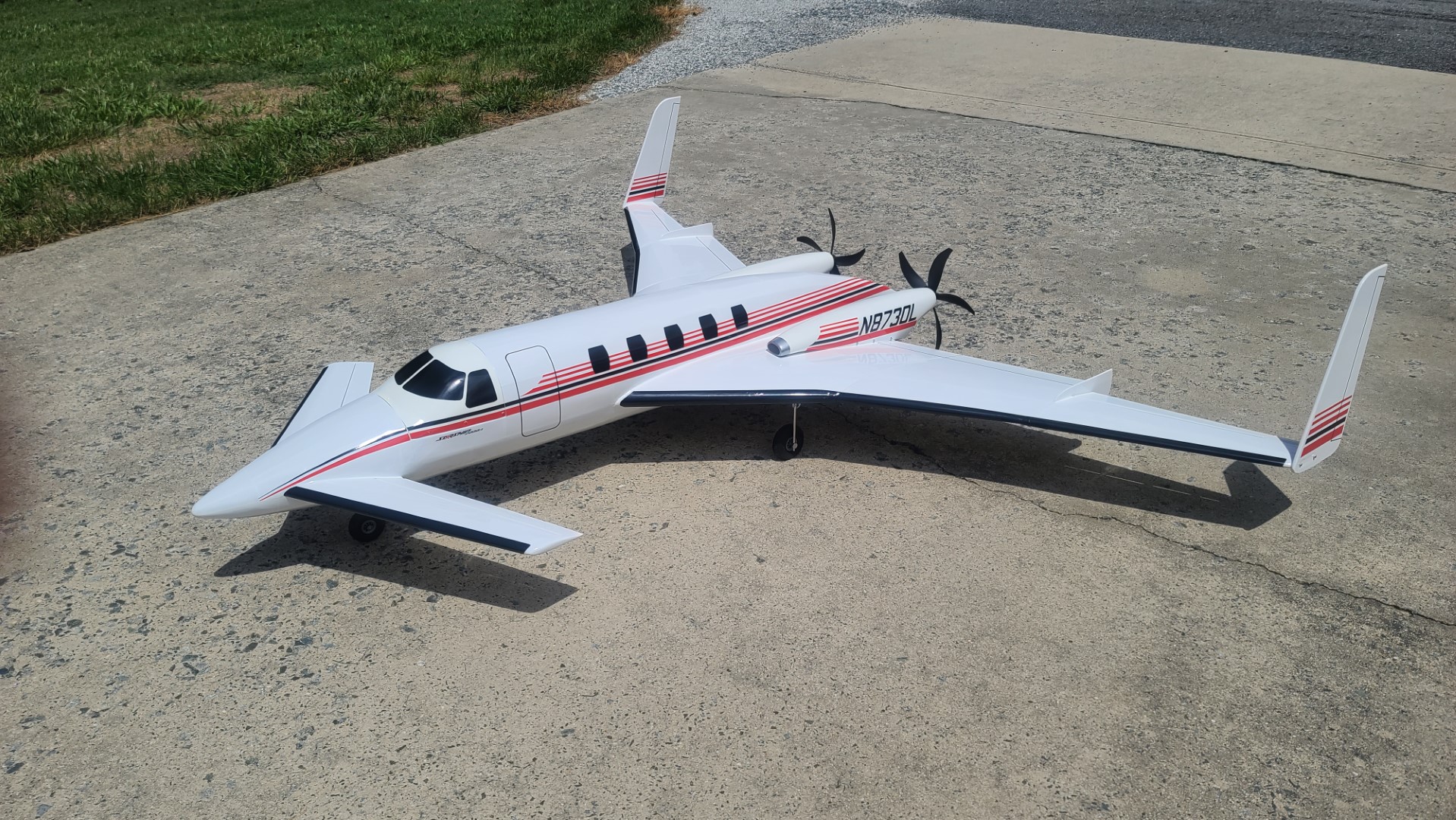
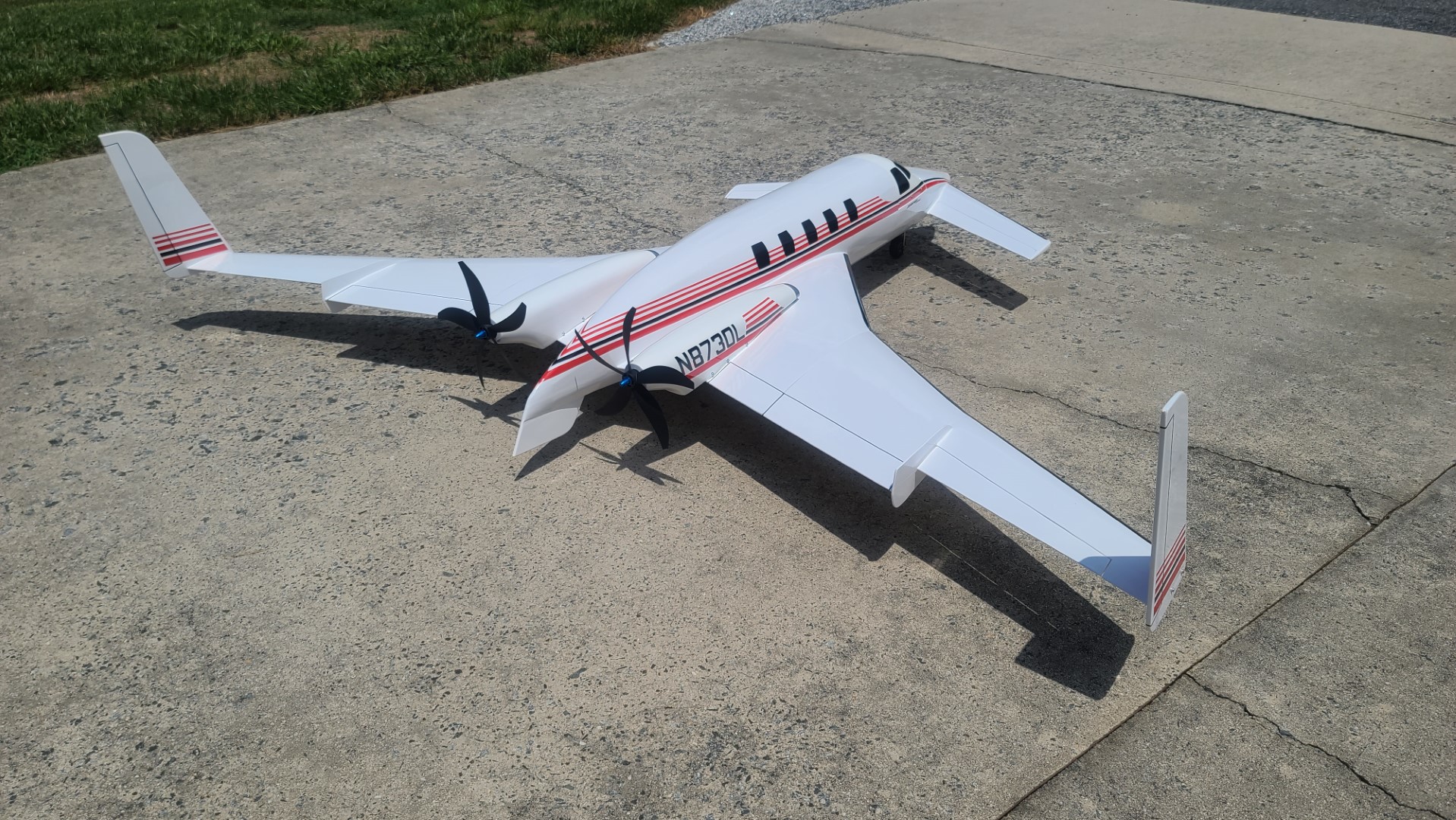
The AMTN kit shown in the top image to the left, and the HIMARK Aircraft Mechanics Electric Retracts were brought to me on 5 April 2024. A "Callie-Graphics" package was used for most of the decals. As you can see in the two images of my completed build to the left, she is a very unique aircraft indeed.
You can see more images and read additional information about the kit @: AMTN Starship. There also is a GREAT multi-part “Plane Fun R/C Channel” Build Log by Saul that you can view @: Starship Build.
We made several modifications to the AMTN kit. The major one was moving the two motor LiPos and ESCs from inside the motor mounts forward to a large fuselage bay area located under the cockpit canopy. This required that we move the receiver from that upper bay to a new bay which we created on the bottom side of the fuselage. All kit modifications are covered in my build description.
My build of the AMTN kit was completed on 3 August 2024. Our Starship is powered by two Sunnysky X3120-KV880 motors using two Spektrum SPMXAE1060 ESCs and two SMC 4S 2,800mah 45C LiPos. Man, those Sunnysky X3120-KV880 motors turning 10x9 Scimitar 5 Blade Props put out some tremendous thrust. Model flight control is provided using a Spektrum AR8360T, AS3X and SAFE, 8 Channel Receiver, with Blue Bird BMS-127WV+ servos for both elevators and ailerons, and a Hitec HS-5087MH servo for NLG steering. The covering is Ultracoat Gloss White with the fiberglass motor cowlings and plastic cockpit canopy painted with Krylon Gloss White and Rust-Oleum Clear High Gloss spray paint. Final total “ready-to-fly” weight came out right at 6,353 grams (14 pounds). Considering this RC model has an overall wingspan of 2,000mm (78.7″); canard span of 860mm (33.9″); a total length of 1,600mm (63″); all the internal structure built using 3mm Lite ply which is then totally sheeted with 1.5mm balsa; add three mechanics electric retracts, two large motors, two ESCs, and two LiPo battery packs, that's not too bad.
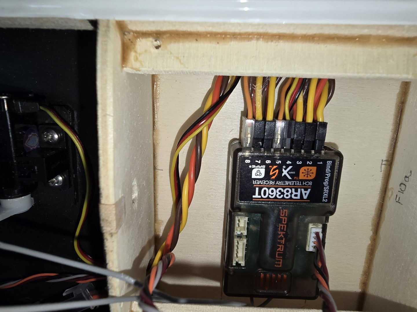
Latest update received from David on 24 Aug 2024. As you can see in the two bottom images, he has installed his Spektrum AR8360T receiver with all eight data ports and the remote receiver port filled. He indicated he has installed the batteries, verified all the servos are correct to the flight control mapping he established for the Starship, set all control throw directions and travel. You can also see the two antenna leads will go into small plastic tubes to ensure they remain 90 degrees to each other. More to come from David, I'm sure.
Should you have any questions about this build, please feel free to send me an email @: Starship.
AMTN Beechcraft Starship Website.
My Starship Build Description with LOTS of Builders Notes.
See All Images Taken During the Starship Build.
AWESOME RCGroups.com Build Log of a Quarter Scale Starship.
Andy Clancy's Speedy Bee
After publishing the August 2023 Edition of my "Build of the Month" Series, I decided to start yet another scratch build to keep me busy over the winter months, and that being the Andy Clancy Speedy Bee. As I worked through my scratch build, I posted new build images such as those to the right, and update my build description which you can obtain via the link provided below. After finishing my build I made the decision to change the main landing gear from the rubber band suspension per the plans to an oil filled shocks/springs suspension.
Maiden flight finally accomplished on 2 May 2024. Had to make an adjustment to the elevator setting, but after that she flies great. The balloon tires and Traxxas oil filled shocks/springs make landings nice and smooth and the ground handling is well behaved. Overall, a fun plane and this one will see lots of flying. I hope you will enjoy this scratch build as much as I did. If you have any questions, just send me an email.
My Speedy Bee was built from a great set of Andy Clancy plans and assembly manual, and RCM article, which are available from: Outerzone Speedy Bee Webpage; and/or Aerofred Speedy Bee Webpage.
Final Version of My Build Description.
See All Images Taken During this Speedy Bee Scratch Build.
.jpg)
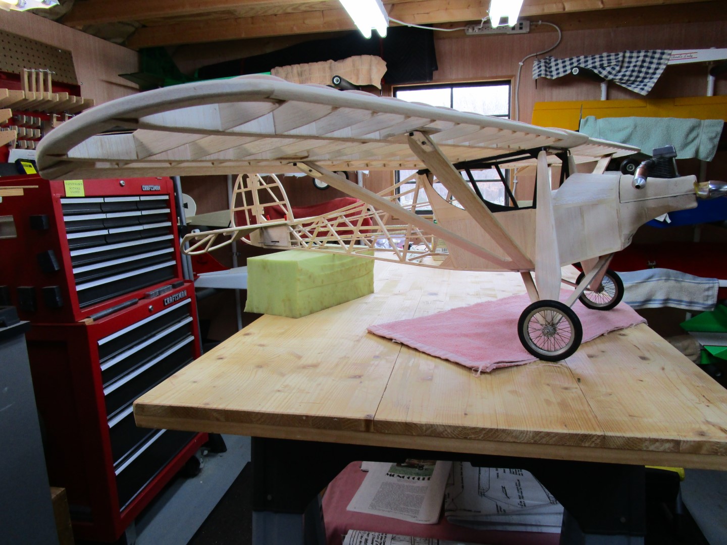

1929 Velie Monocoupe
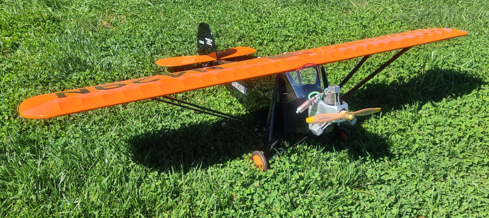
The Velie Monocoupe Model 70 was one of the first airplanes ever built for private fliers. A total of 350 Velie Monocoupe were built from 1927-1929. The Velie Monocoupe was a wooden framed, doped fabric-covered monoplane, seating two people side-by-side in an enclosed cabin (hence the name). Conceived by pilot/businessman Don A. Luscombe, who developed a mock-up in 1926, and developed into a flying airplane by farmer-turned-plane-designer Clayton Folkerts—first produced by Central States Aircraft Corp in Davenport, Iowa—the little plane was a revolution in personal aviation: small, relatively inexpensive, quick, and efficient (70-80 mph on just 55 horsepower), and with an enclosed cockpit (protected from the weather) for two people. In an era of big, costly, lumbering, open-cockpit biplanes, the Monocoupe was like a flying sports car coupe. Powered by the little 55 hp Velie five-cylinder air-cooled radial engine and a wingspan of 32’, the model 70 Monocoupe was a very successful airplane. The company sold so many units in 1928 that they were able to claim that 80 percent of the civilian airplanes sold in the U.S. in that year were Monocoupes.
The free 1929 Velie Monocoupe plan and article were downloaded from "Aerofred.com" and are also available from "Outerzone.co.uk." The Velie in this build was designed by Jack de Vries, Colonel U.S.A.F., and the article is from a January 1973 Radio Control Modeler (RCM) magazine. This 40-size version has a wingspan of 66", an overall fuselage length of 45", and is designed for a .30 - .60 cu. in. engine. I installed a Thunder Tiger .54 4-stroke my father used many years ago. With the wing being longer than my magnetic build board, this build will be accomplished using the old wood build board pin-in-place method. The Velie is a good stick build for anyone with some basic woodworking skills, but I would not say it should be considered for your first scratch build project. While doing some web research for my build I came across a very nice build log on "RCGroups.com" for the same plans. Reading thru that post I learned some new (for me) build methods which I adopted in my build.
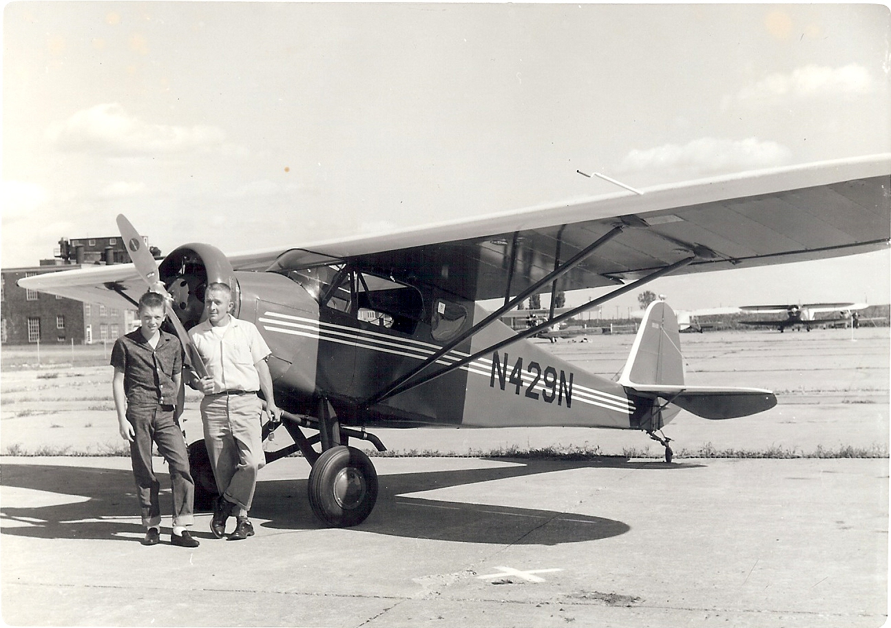
The images on the left are: top - a 1929 Velie Monocoupe Model 113 from Aerial Visuals; 2nd - my Velie RC model fit checks; 3rd & 4th - my completed Velie RC model; bottom - my fathers 1932 Monocoupe Model 90 at the 1963 AAA fly-in, and yes that is me with my father who restored N429N, which is now on display at the Old Rhinebeck Aerodrome, Rhinebeck, New York.
My Velie was built from a great set of plans and RCM article, which are available from: Outerzone Velie Webpage; and/or Aerofred Velie Webpage.
My Velie Build Description.
See All Images Taken During this Velie Scratch Build.
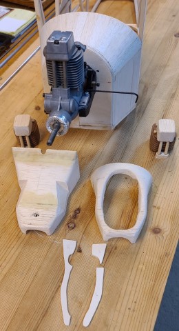
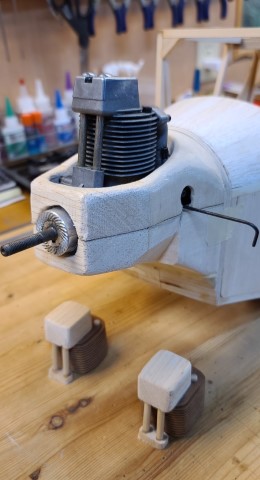
Old School Build
Here are a couple images that show some “old school” building techniques. These are from my 1929 Velie Monocoupe that I started in winter 2022, and was completed in March 2023.
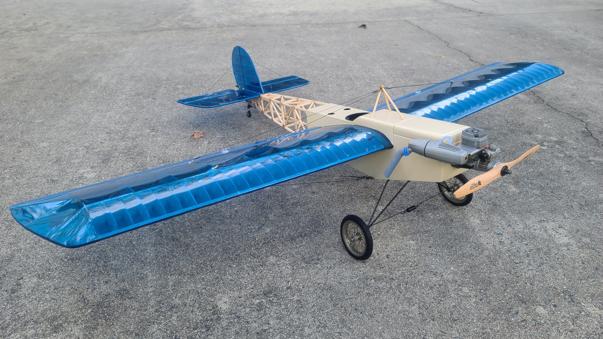
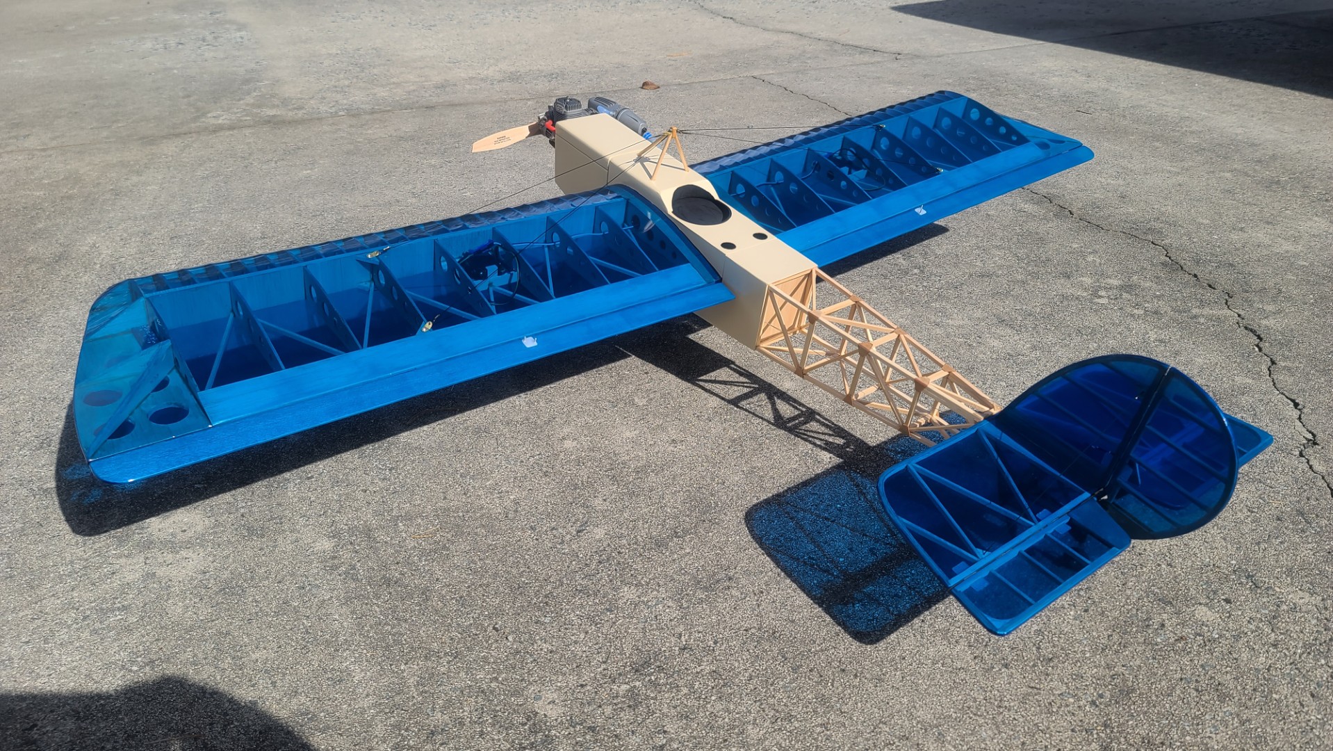
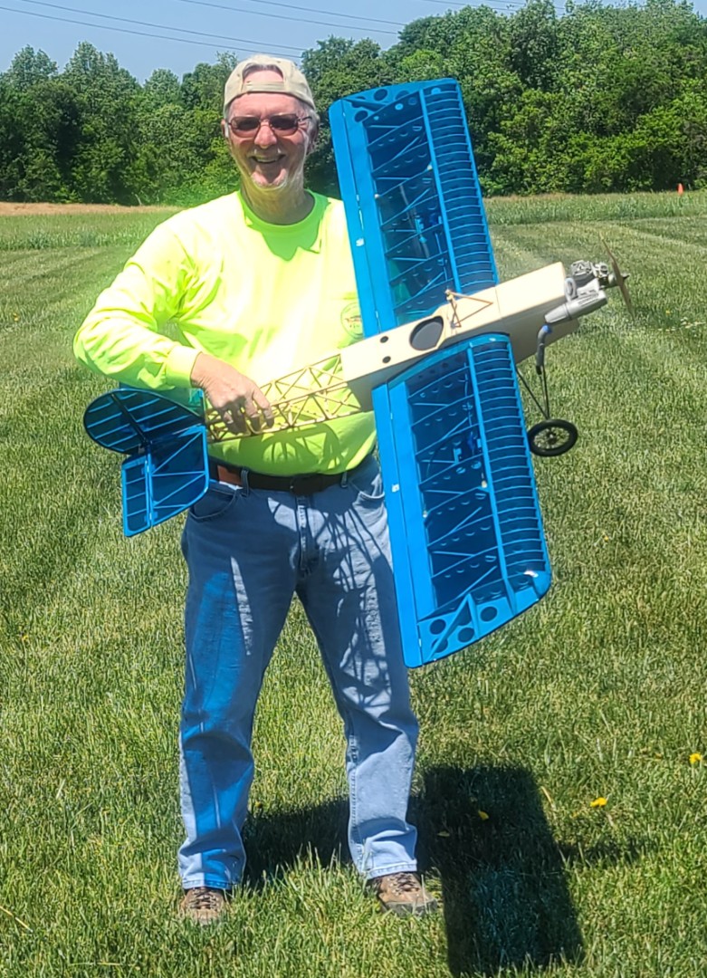
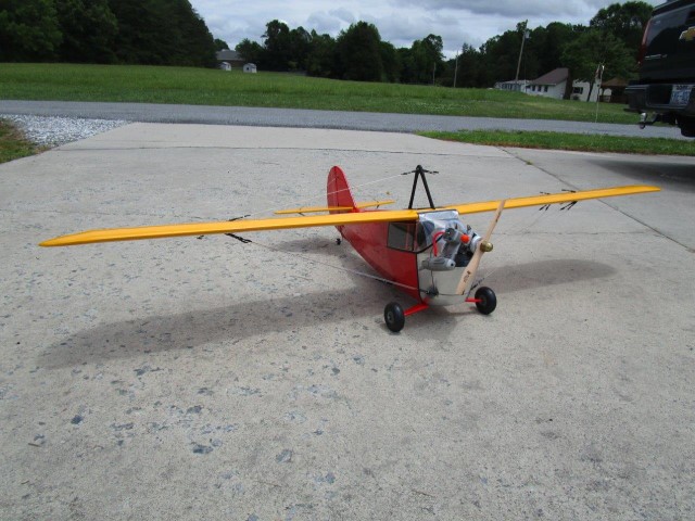
STOL Pigeon
The free STOL Pigeon plan and article were downloaded from "Aerofred.com." This is a GREAT site to obtain plans for scratch builds.
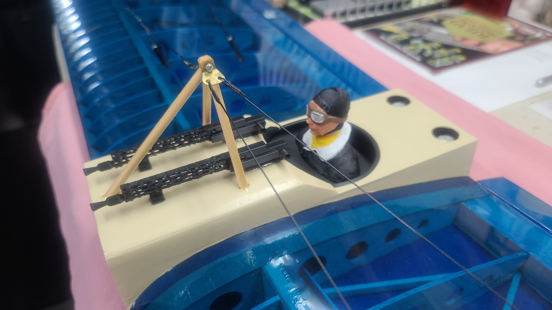
The construction of this model is very straightforward. Simplified wings give all of you scratch builders a well-deserved break. The ribs are spaced as far apart as practical, and the wings are identical in all respects. The rib spacing allows a mere 38 ribs to be used for both wings. That number is very close to most 2-meter gliders, but remember, you get all the nostalgia of two wings for the building time of one.
This is a great plane for the first-time scratch builder to build and fly. I modified the plans to use "bolt-on" wings (template found on “BalsaWorkbench.com”,) increased the rudder by 30%, extended both wings to 48" removed the dihedral, and put an O.S. .35 2-cycle in for power.
I used five channels in this airplane but that is not to say fewer could not be used. This biplane has been flown on three channels and it even does well on two channels. The reason for the five channels in my aircraft is that I tend to get frustrated with a slow aircraft if I can't do aerobatics and have lots of functions to play with.
First step in most of my builds is to print out a copy of the full-size plan on my Canon printer using the "poster" settings, and then put all the pages together for an overall 77" x 42.5" plan on two sheets. You can also get the plan printed out at Fed Ex for around $25 a copy. Having the full-size plan, I then went thru and determined all the materials I would need to make the build. Any balsa sticks and sheets, basswood or plywood needed were ordered from Balsa USA.
My STOL Pigeon was built from a great set of plans and RCM article, which are available from: Outerzone STOL Pigeon Webpage; and/or Aerofred STOL Pigeon Webpage.
My S.T.O.L. Pigeon Build Description.
See All Images Taken During my S.T.O.L. Pigeon Scratch Build.
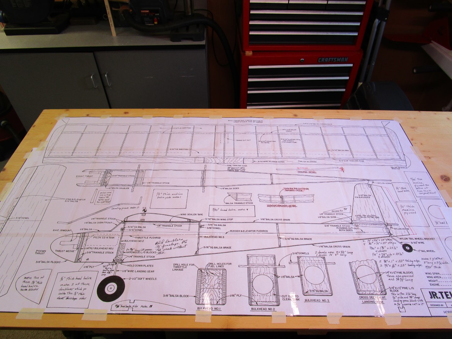
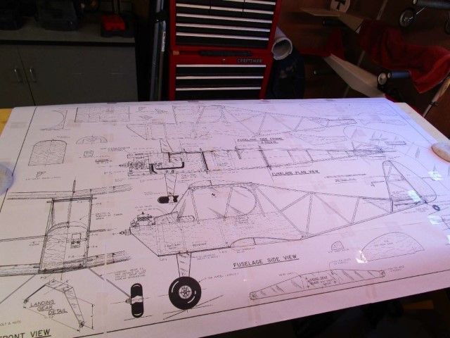
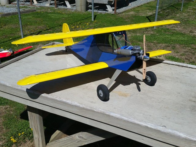
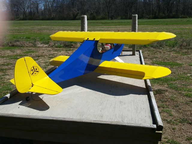
Junior Telemaster
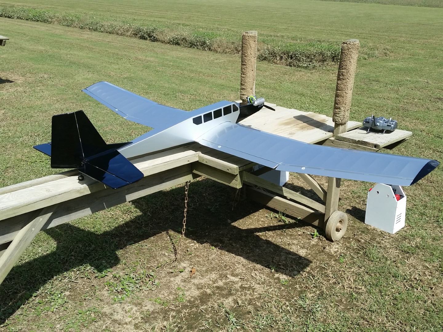
You want a scratch build that is very simple, will not require a lot of materials, and results in a GREAT trainer? Then this little balsa and ply RC model is just what you want to try. Anyone that has been to an RC flying field has probably seen some version of a Telemaster in one size or another. The Telemaster is a classic RC design that thousands of modelers have built and flown for generations. An exclusive mainstay of the Hobby Lobby brand, anyone who learned to fly in the 1960s, '70s, or '80s knows that the Telemaster in its various sizes is a popular, easy-to-build, great-flying airplane. Even today, if you have not actually flown one, you certainly know someone who has. Originally produced by Alexander Engel of Germany and imported to the United States by Hobby Lobby International in the late '60s, the Telemaster spawned three versions of kits (and even ARFs): the standard 6-foot-span model, the 8-foot-span Senior Telemaster, and the 4-foot-span Junior Telemaster, making it one of the oldest, continually produced airplane designs available today.
A classic part of the Hobby Lobby lineup of kits for decades, the Telemaster was retained when Mark Cleveland purchased Hobby Lobby and changed its name to Hobby Express. Mark has been working with Treeline Development to expand the Telemaster heritage and introduce it to a younger generation of makers by forming an approved STEM (Science, Technology, Engineering, and Mathematics) development course. The curriculum is planned to be compatible as a stand-alone class, a work-study job, or an after-school program in which high-school students will learn the basics of quality control and safety while meeting the demands of manufacturing a full-production product. It goes without saying that the program will also encourage student engagement in ideation and entrepreneurial thinking and RC model aviation!
I think the Telemaster is an ideal trainer. With or without ailerons it responds positively to the controls and goes where you point it even in moderate winds. The controls are effective down to the stall point, which is gentle and occurs at a very low speed. It is moderate in size for economy and ease of transportation, yet has plenty of room for radio equipment. Also, it is strong without being heavy or difficult to build. This version is called a “Junior Telemaster”, and can be powered by nitro engine or electric motor. Mine is powered by an old O.S. .26 4-stroke engine, and is a joy to fly.
My Jr. Telemaster was built from a great set of plans and Flying Models article, which are available from: Outerzone Telemaster Webpage; and/or Aerofred Telemaster Webpage.
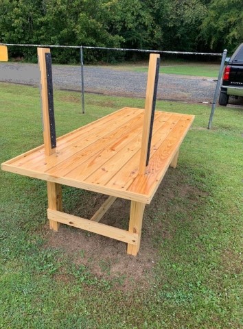
New Big Tables
Along with picnic tables and standard starting tables, I built a number of these flat top tables for R.G. Satow RC Flying Field. I created a PDF file with instructions and a complete bill of materials if you would like to build one for your own use at home. Click the link to download or view the instructions.

My Cloud Dancer Build Description.
Cloud Dancer “2026 TAI Swap Meet Raffle Prize” Flyer.
See All Images Taken During my Cloud Dancer Scratch Build.
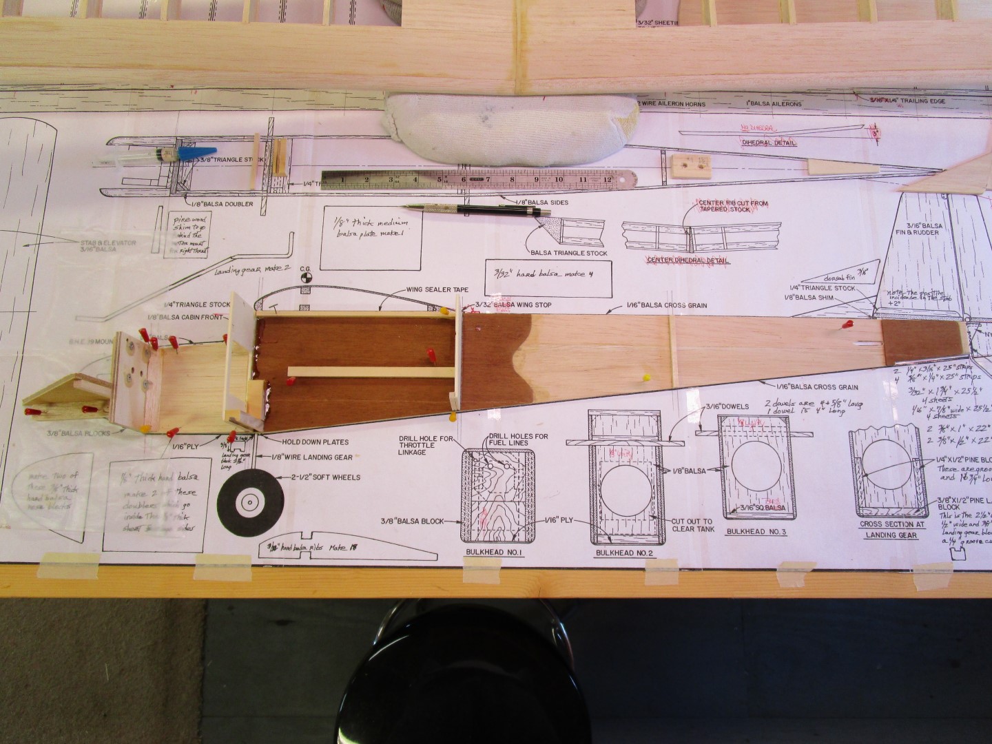
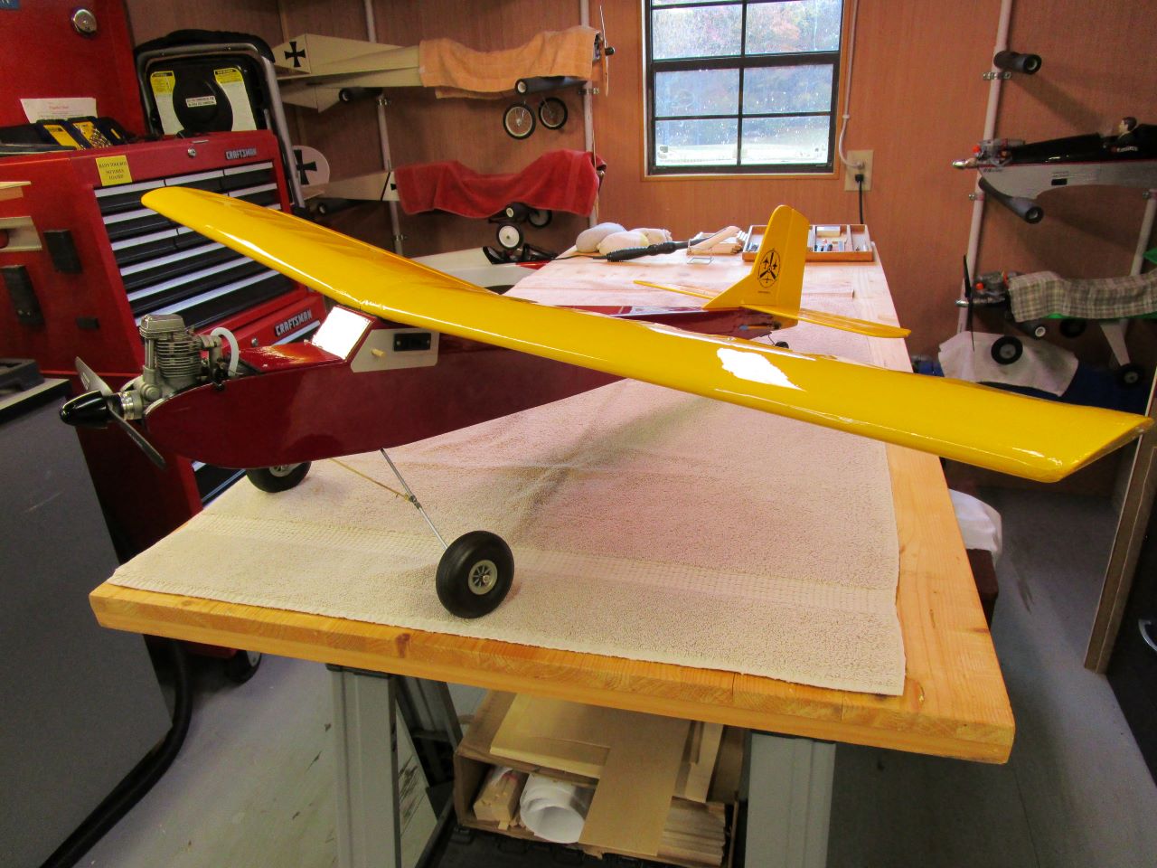
Cloud Dancer
The free Cloud Dancer plan and article were downloaded from "Outerzone.co.uk", but plans can also be found on "Aerofred.com", which has several versions of the Cloud Dance ranging from 40" to 86" wingspans. There also is a laser short kit for the larger Cloud Dancer 120 available for purchase on "The Balsa Workbench."
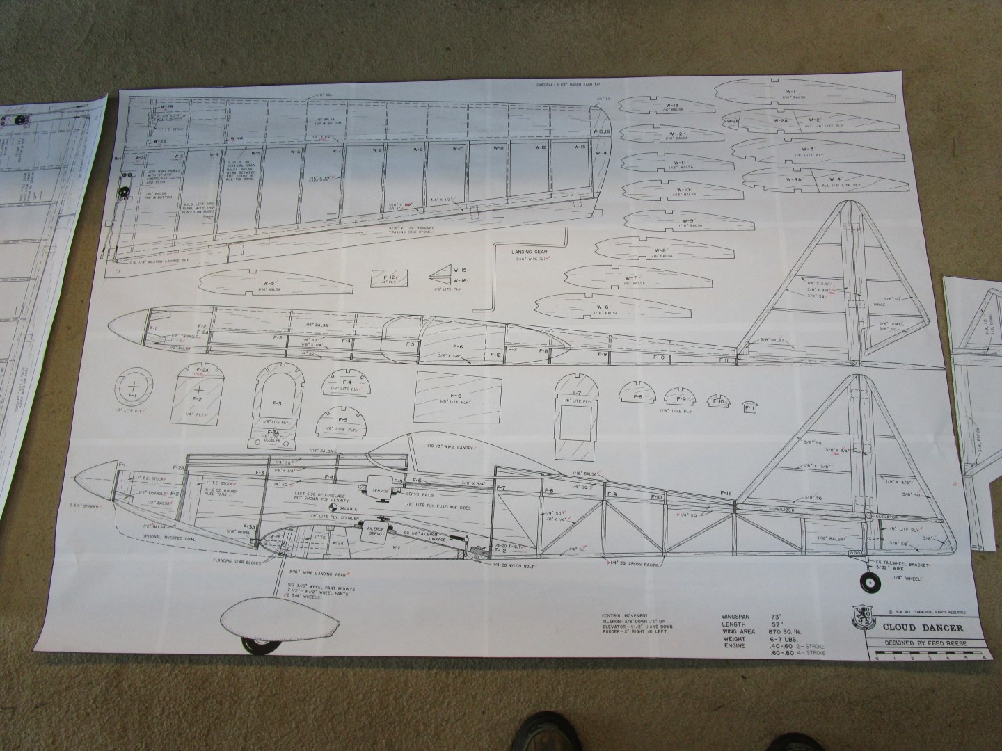
The Cloud Dancer I built was designed by Fred Reese, and the article is from a June 1993 edition of Radio Control Modeler (RCM). This .60 size version has a wingspan of 73" with a total wing area of 850 sq. inches, which will result in a light wing loading of approx. 17 oz. per sq. in. The overall fuselage length is 57", and is designed for a .40 - .60 two stroke. I installed a Thunder Tiger .61 2-stroke my father used many years ago.
First step in this build was to print out a copy of the full size plan on my Canon printer using the "poster" settings, and then put all the pages together for an overall 77" x 51" plan.
Given the plan only has the right wing and right horizontal stab drawn, I inverted the plan file vertically to get a left wing and stab, and that copy of the plan was cut up to get the patterns for all the ribs, formers, fuselage sides, etc.
You can also get the plan printed out at Fed Ex for around $25 a copy.
My Cloud Dancer was built from a great set of plans and article, which are available from: Outerzone Cloud Dancer Webpage; and/or Aerofred Cloud Dancer Webpage.
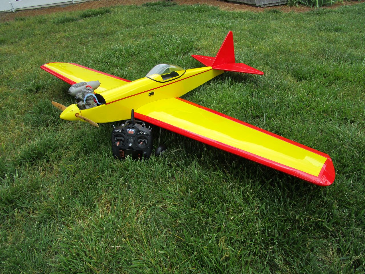
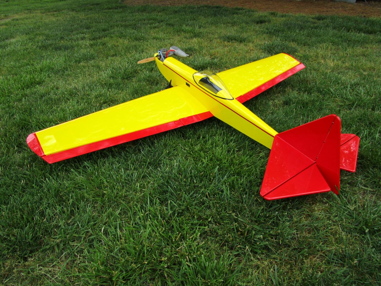
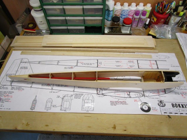
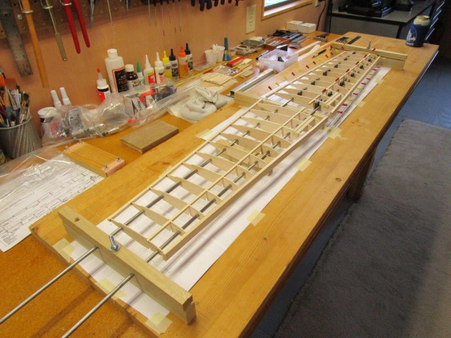
Bokkie
This low wing .20-.30 powered sport flier builds quick, flies great, and won't break the bank.
Here is a link to download the Full Size Plans and the February 1971 RCM Article, both from AeroFred Bokkie Webpage.
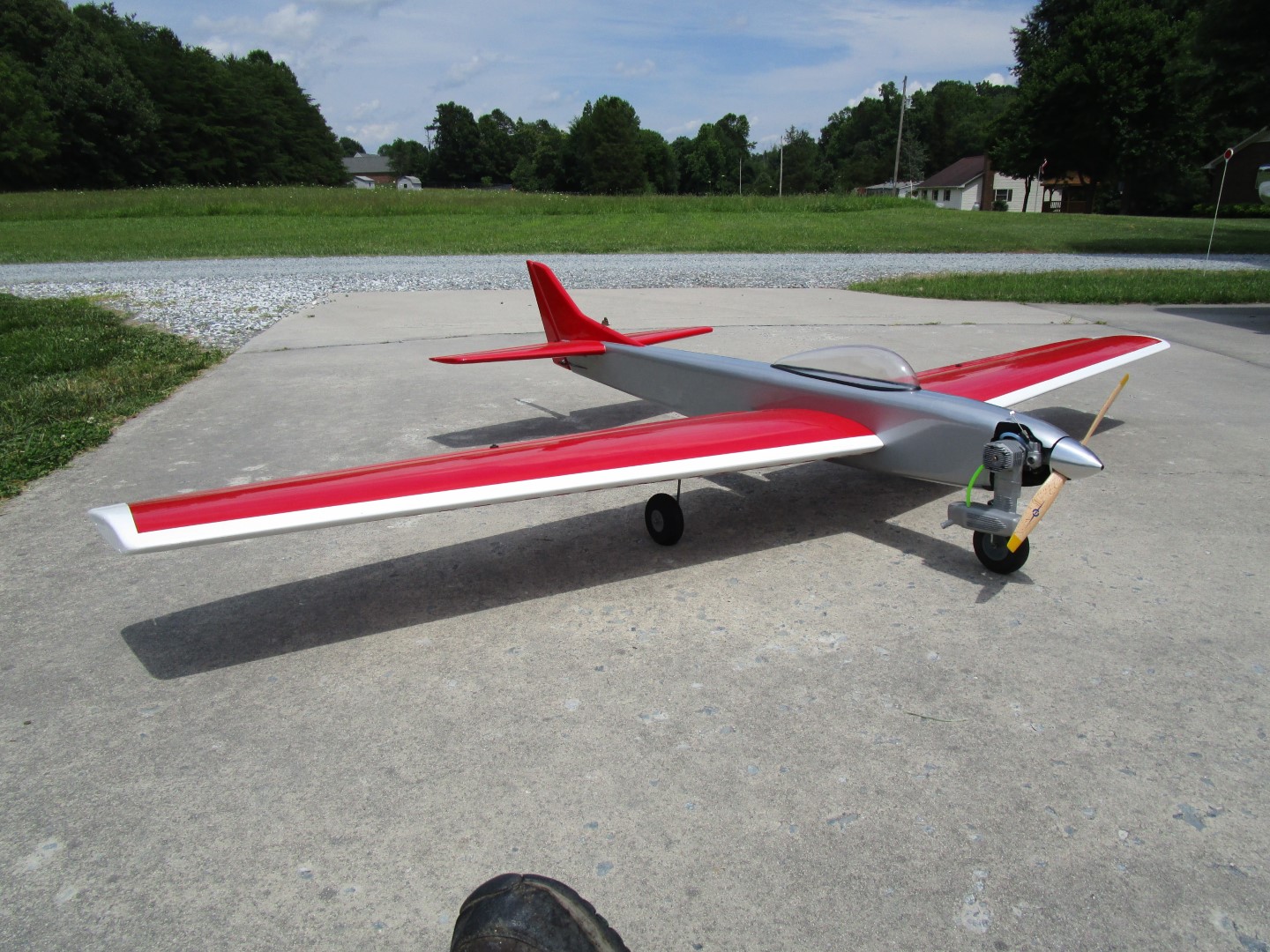
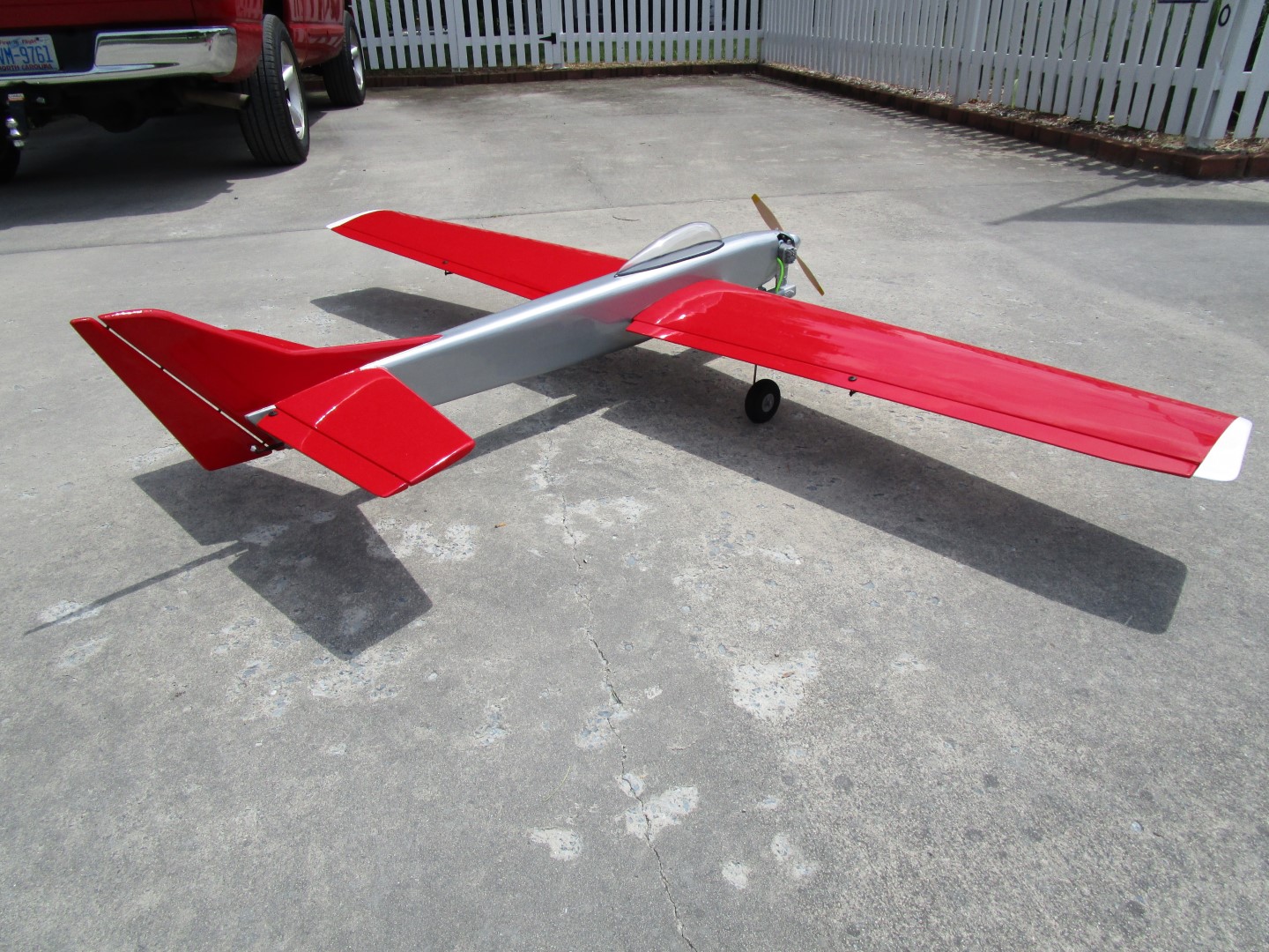
150% SIG Wonder
My original SIG Wonder was getting too small for my aging eyes, so I built a 150% version. Powered by an O.S. .45 FX she flies great, and is still just as fast and responsive as the little Wonder.
Original Wonder Full Size Plans from SIG.

My Big Bird II was built from a great set of plans and article, which are available from: Outerzone Big Bird II Webpage; and/or Aerofred Cloud Dancer Webpage.
My Big Bird II Build Description.
Big Bird II
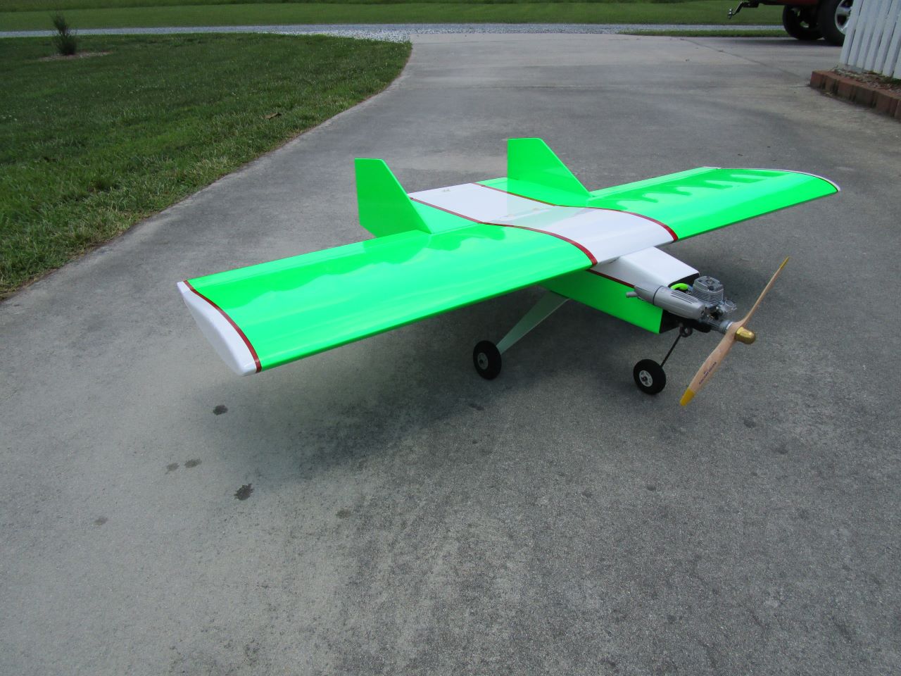
This build is very similar to the Dynaflight Butterfly plane. The construction is very straightforward. A basic LONG box fuselage, stick built tail surfaces, and a BIG flat bottom wing. This would be a great plane for the first-time scratch builder to build and fly. I modified the plans to use "bolt-on" wings, added ailerons to each of the outer wing panels and flaps to each of the inner wing panels, increased the rudder and elevator by approximately 30%, extended each of the inner wing panels to 23", which yields an overall wingspan of 94", and removed the dihedral at the wing center section joint. There are some other modifications which I call out in my build description that I've provided to the right. I initially used an O.S. .26 Surpass 4-cycle for power, but later changed to an O.S. .25 FX 2-cycle so I could use the 4-cycle on another model. I elected to use five channels in my scratch build but that is not to say fewer could be used if you did not want the ailerons and/or flaps, or more can be used if you want to drive each flap and aileron surface servo using a separate channel on the receiver. It is your call on this one.
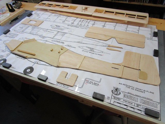
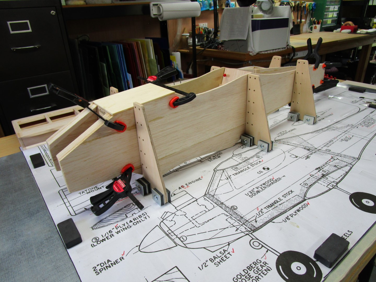
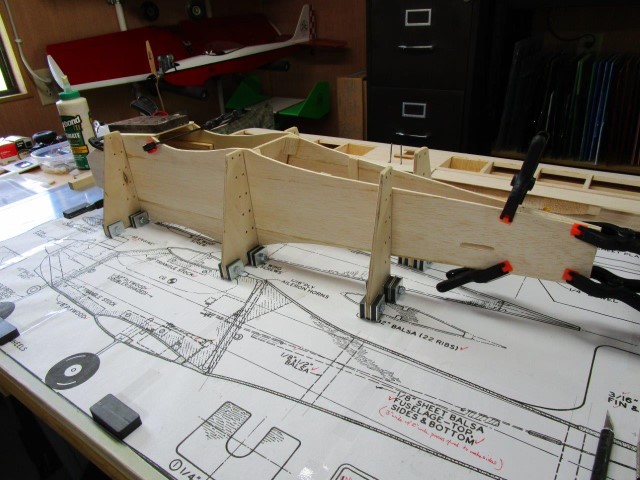
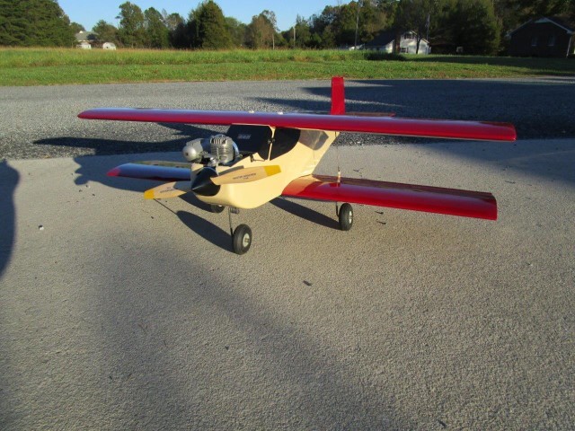
Double Trouble 40
She has a wing span of 36.5", overall length of 38", and is powered by an O.S. 46LA. A very simple build, and she turned out to be an interesting aerobatic biplane.
Link to download the Full Size Plans and the February 1978 RCM Article, both from Outerzone Double Trouble Webpage.
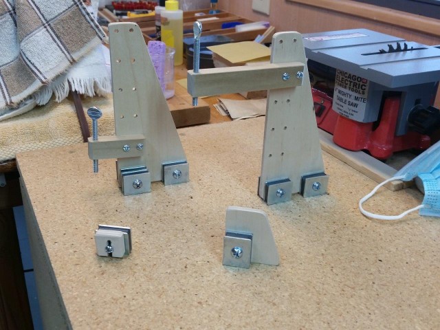
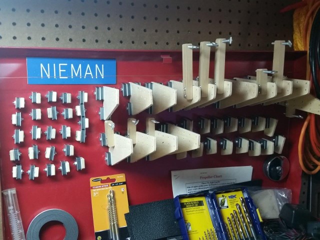
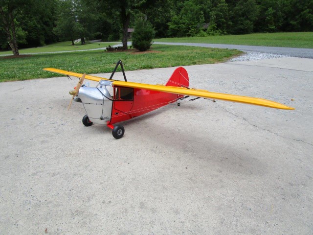
Magnetic Build Board & 1935 Aeronca C-3
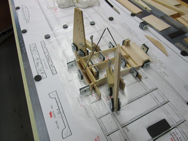
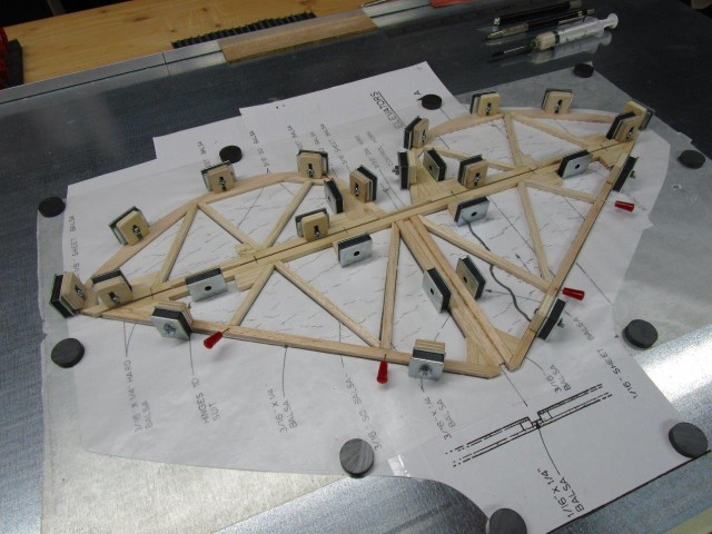
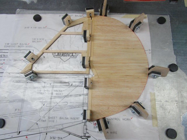
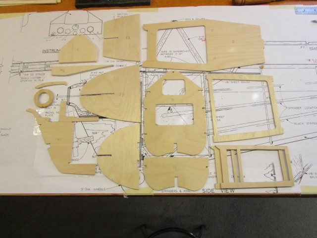
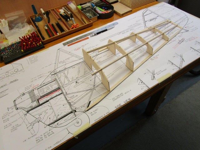
The Results: A scratch built 1935 Aeronca C-3. Six foot wingspan and powered by an O.S. .35 2-cycle.
Here are the links to download the Full Size Plans and the January 1974 RCM Article, both from AeroFred Aeronca C-3 Webpage.
Lots of good info here, and is where I got the info I needed to make my magnetic building board and all the various fixtures.
Another good source of magnetic build board information and many different types of fixtures that you can purchase.
Ed Kazmirskis' Simla
The Simla was RC pioneer and legend Ed Kazmirskis' boldest and most ambitious design. In 1965 the Simla was a giant leap into the unknown world of large-scale RC Aerobatics (Pattern) airplanes, decades before big models would be commonplace. The Simla was an experimental, one-of-a-kind effort employing out-of-the-box thinking at a time when aircraft design was as much intuition as scientific. It featured adjustable high-, mid-, and low-wing positions; adjustable dihedral and stabilizer incidence; and, best of all, an early form of plug-in wings in an era when dowels and rubber bands were holding all other models wings on. Plans for the Simla can be ordered from the Model Aviation Magazine Plans Service. You can find a link to their site on my "RC_Links" page by simply clicking on the “AMA Plans Service” link.
The Model Aviation Article that got me interested in scratch building the Simla.
My Simla Build Description.
My Simla Material List.
See All Images Taken During my Simla Scratch Build.
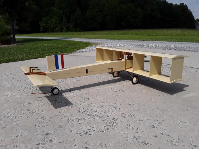
1911 Voisin Canard
A Truly Different Aircraft
The Voisin Canard was an aircraft developed by the Voisin brothers during 1910 and first flown early in 1911. It was named the Canard because of the resemblance of its forward fuselage to that of a duck's long neck while in flight. It was originally flown as a land plane: with the addition of floats it became one of the first seaplanes used by the French Navy.
My Voisin Canard was built from a great set of plans and article, which are available from: Outerzone Voisin Canard Webpage; and/or Aerofred Voisin Canard Webpage.
My Voisin Canard Build Description.
See All Images Taken During my Voisin Canard Scratch Build.
A short video of my Voisin Canard actually flying.
.jpg)

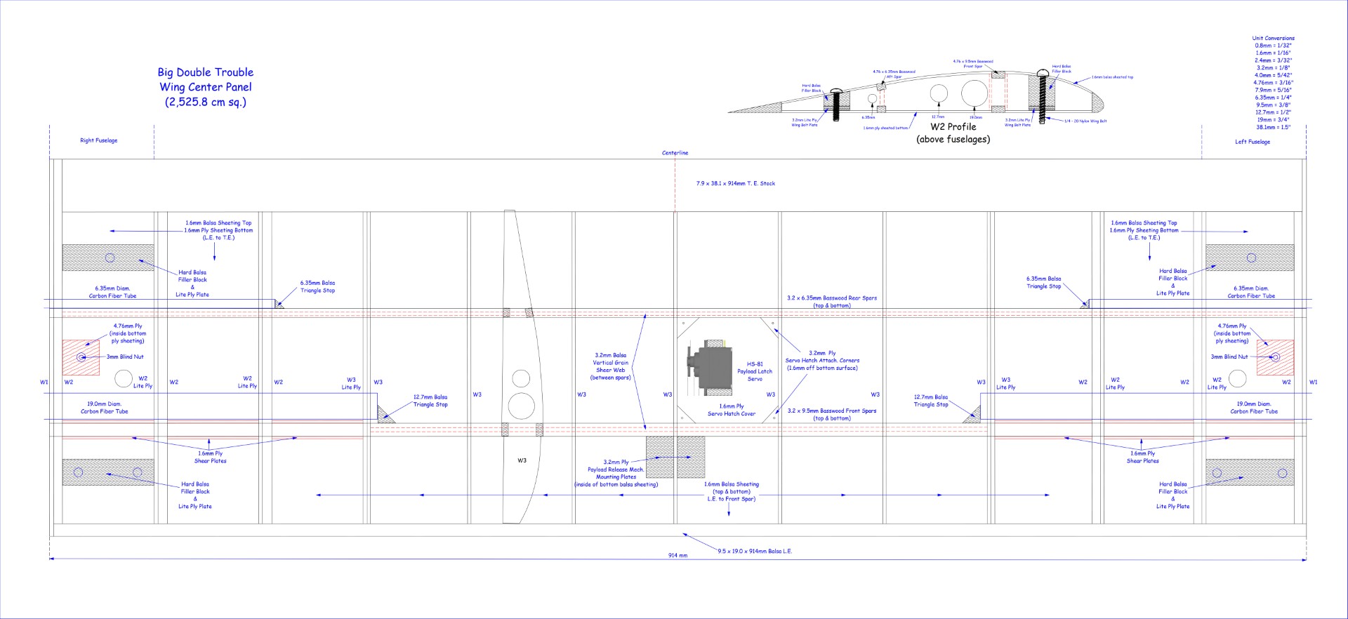
Big Double Trouble
and X-20
When I first saw the Virgin Galactic White Knight Two and Spaceship Two back in 2008, I thought it would be interesting to see if these two aircraft could be built as RC models. As with the two Virgin Galactic aircraft, the mothership model would carry a smaller aircraft model to altitude and then released to allow another member of our flying club to control its flight using a separate transmitter. I searched the web for any existing plans but came up with zero. So, I decided that I would come up with something myself.
My White Knight Two model would be similar in having two fuselages, a very large wingspan, and a center wing section that could carry a smaller captive carry RC model. Because of its very gentle handling characteristics, known flying qualities, and rather simple design, I decided to use the plans from my Dynaflight Butterfly kit as a starting point, and then made many additions and modifications from there. The largest difference was this would be a twin fuselage model using two 4-cycle engines for power, and a wingspan of 152 inches overall. Not a small model. Details of this build are contained in my build description which is provided below.
Big Double Trouble Hand Drawn Plans Conversion
Many years ago I drew up some plans using paper, pencil, and ruler for my Big Double Trouble (shown above). You can read more about this and the scratch build in My Double Trouble Build Description.
As I had stated in the build description “With my hand drawn plans, I don't have a pdf file that you can download. Sorry. Maybe someday I'll get the plans scanned into a pdf file, or maybe even try and work the plans up in a CAD program.” Well, that time has come. The plan is to convert my hand drawn 2D plans into a set of digital files using my 2D CAD program Back To The Drawing Board. I will incorporate the various changes I made to my hand drawn plans during my scratch build of the model, and even add whatever modifications are needed for an electric powered version. Once these are finished I will post all the plans to this section so anyone interested can download them, and also share them with AeroFred and Outerzone so they can be posted to their websites.
Heck, I might even get motivated enough to build a new Big Double Trouble in the electric powered version.
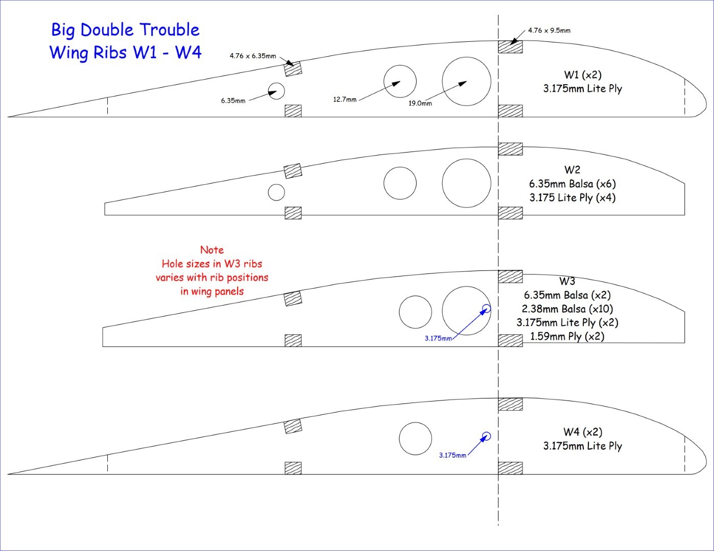
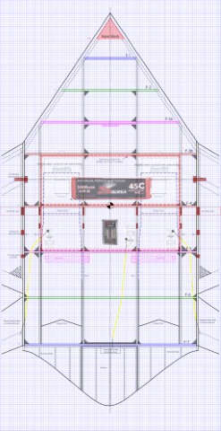
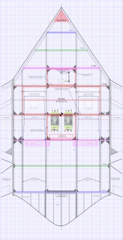
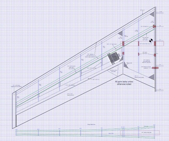
This updated posting is as of 2 May 2026. I started my hand drawn plans conversion with all the wing ribs, then moved next to the wing outer panels, followed by the wing middle panels, and then the wing center panel. So, the entire wing plan has now been converted into digital files. Results of this work can be seen in the four images below.
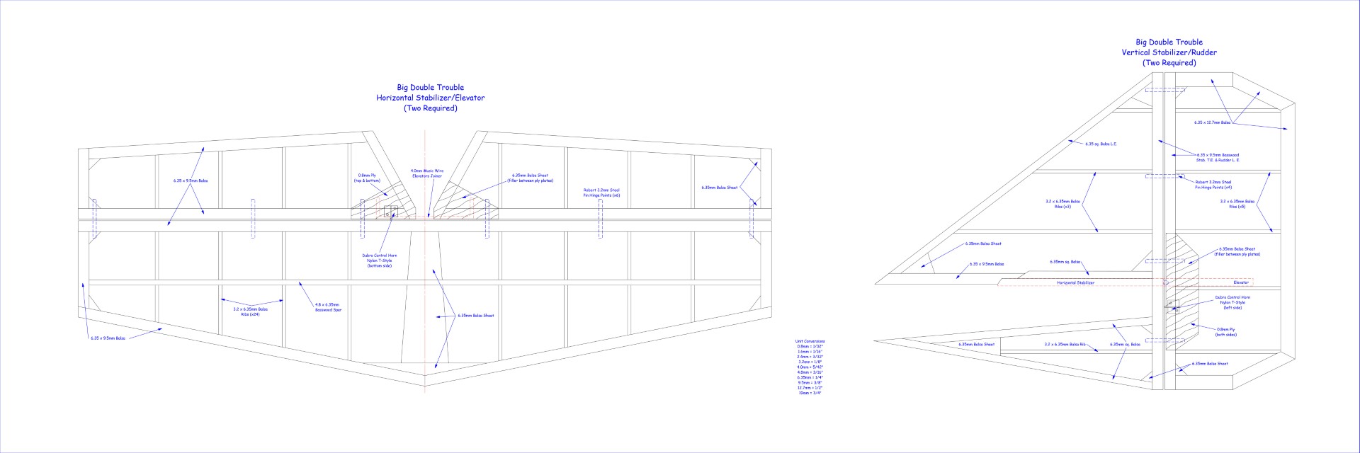
With all the wing plans finished, I decided to convert the horizontal stabilizer/elevator and vertical stabilizer/rudder (I call these tail feathers) plans next. Results of this work can be seen in the next image below.
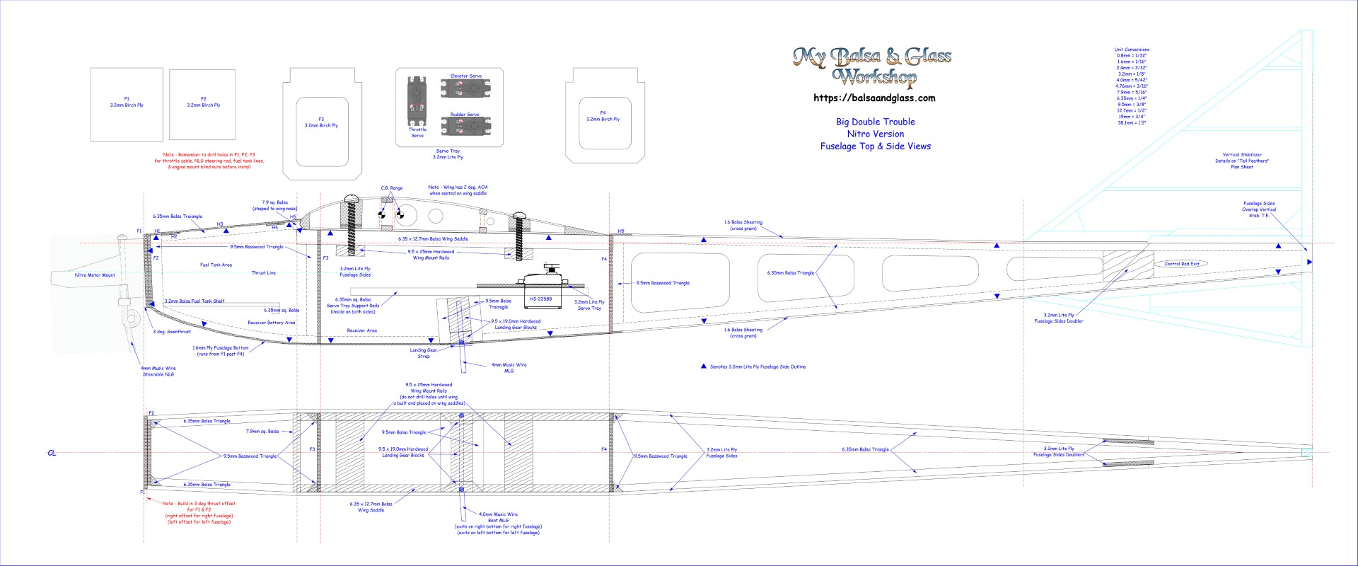
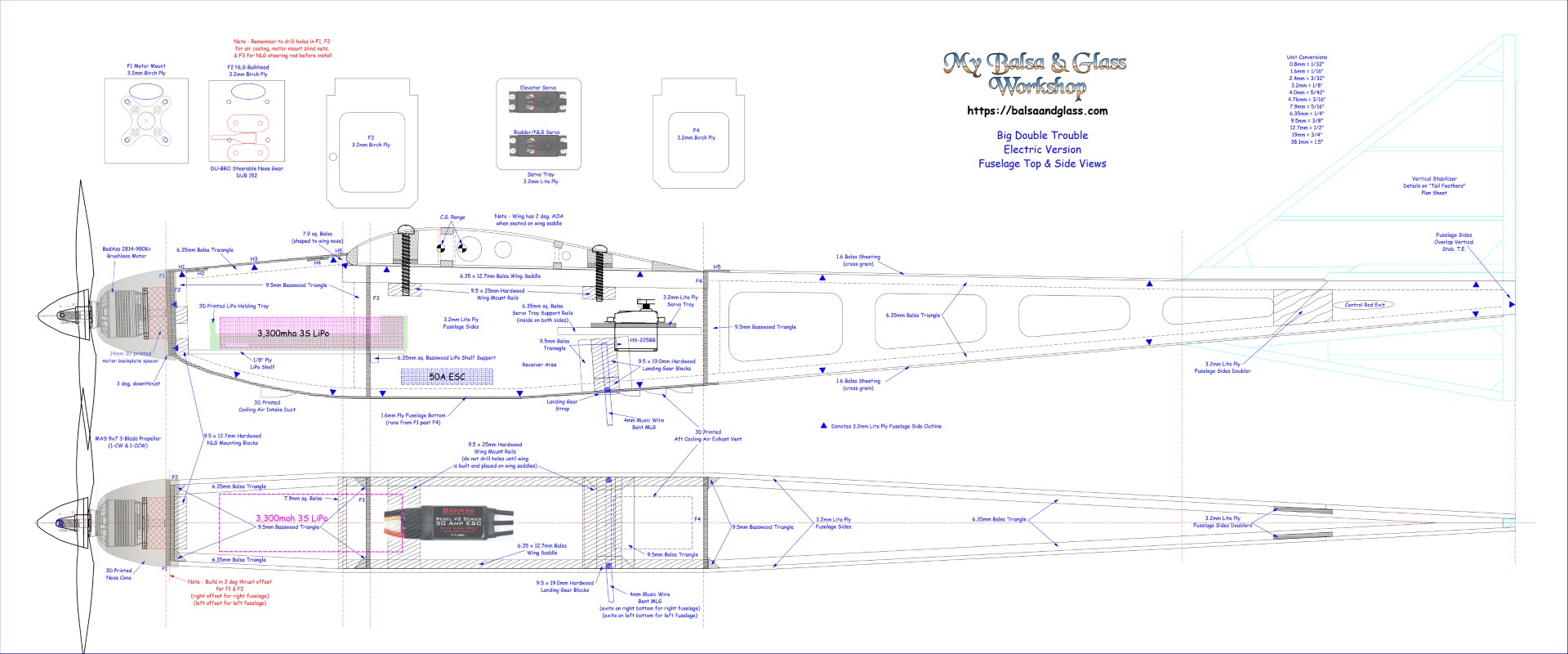
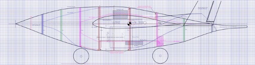
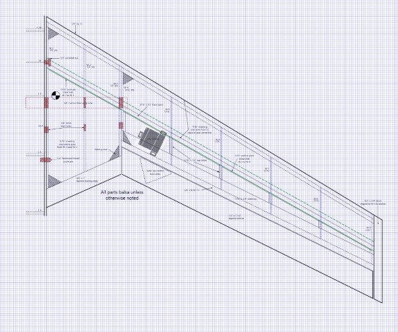
The last hand drawn plan to convert was the fuselage views. I did the original Nitro engine plan for now, but I will work up a fuselage plan for an Electric Powered Version. The Nitro Version can be seen in the next image below.
Alright, now for an Electric Powered Version. First, I established my power system requirements and then selected the required power system components. Based off my original Nitro powered scratch build using two O.S. 0.26 4-stroke engines, and she flew just fine, I decided to go with an electric system having similar power output.
I like using the performance data charts that can be found on the Innov8tive Design Website. Using their charts and needing a power system somewhere in the range of a .25 glow engine for each fuselage, the BadAss 2814 Series of motors fits the bill. The BadAss 2814-980Kv specifications state a Max Continuous Power (with 3-cell Li-Po) of 510 watts (each motor) at Maximum Continuous Current of 46 amps. The 2814-980Kv motor performance data chart lists data for a Master Air Screw (MAS) 10x7 3-blade prop using a 3S battery pulling 28.0 amps and producing 1,492 grams (52.6 oz.) of thrust at 8,471 RPM. So, my BadAss Power System is comprised of the following components: - 2ea. Motors: BadAss 2814-980Kv Brushless; 2 ea. ESCs: BadAss Rebel V2 Series Brushless, 50A; 2ea. Batteries: BadAss 45C 3,300mah 3S LiPo; 2 ea. Props: MAS 9x7 3-Blade. This Power System will provide a total power of 2,984 grams (105.2 oz.). This is the same power system I selected for my 56″ wingspan 1/15th Semi-Scale A-26 Invader scratch build, which is a higher performance model than my gentle, lazy, slow flying 152″ wingspan Big Double Trouble.
With my power system components selected, I next determine where each would need to be placed in the two fuselages so as to try and maintain the required C.G. location, and allow easy installation of the LiPo batteries. I modified my Nitro version fuselage plans to include: changes required to move the Steerable Nose Landing Gear from the Nitro engine mount to the backside of fuselage former F2; moved the Main Landing Gear mounts further aft; addition of a LiPo support shelf; changes to the formers for the motor mount and to make room for the LiPo battery installation; and some cooling air intake/exhaust vents on the bottom of the fuselages to provide cooling air to the LiPo and ESC. As shown below on the latest plan, I even worked up a 3D model in Fusion 360 for a printable nose cone.
With all the various plans finished, I took each of the plans and aligned them together into a single “Total Model Top View” plan. Each of the plans fit together like a glove. The total model plan is shown in the image below.
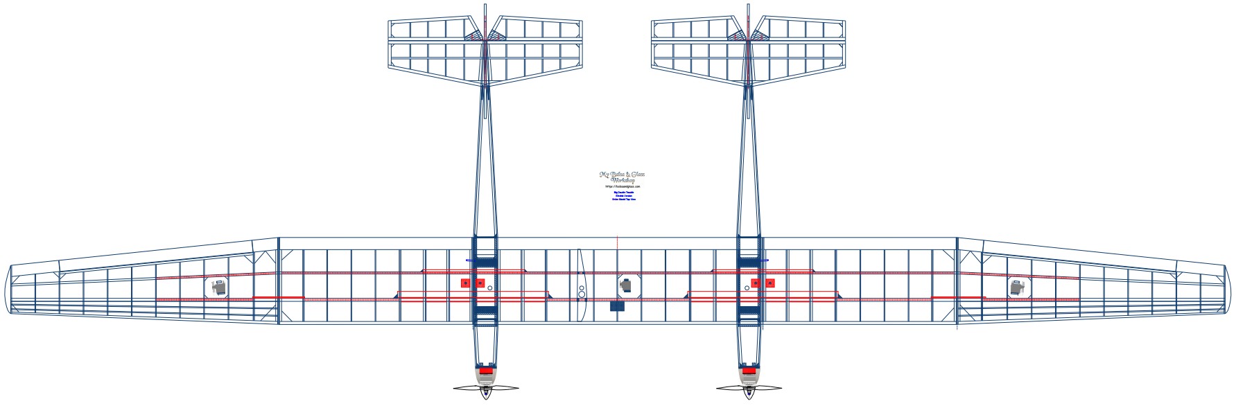
All Big Double Trouble Plans in PDF format.
All Big Double Trouble Plans in DXF format.
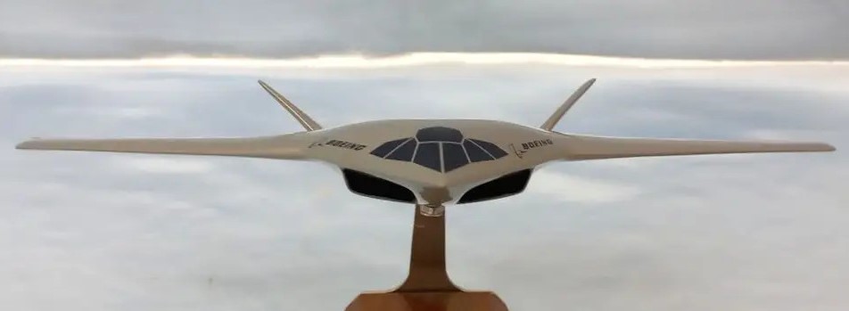

Boeing Blended Wing Body Concept
I'm going to try and draw up some plans for an RC model using two electric ducted fans (EDFs) for propulsion. Something around 48" to 60" for a max wingspan. A built-up fuselage using light ply formers and skinned with 1/16" balsa. Wings as I normally build using a "boxed D" design. I plan to use 5/8 inch carbon fiber tubes to mate the wings to the fuselage. Right now the overall span is 54", but a large part of that is the wide fuselage, which also acts as another large wing like lifting surface. Overall wing loading I hope will end up being less than 20 oz. per square foot. The twin EDF fans will be inside the fuselage, with access panels on the bottom of the fuselage. Tricycle gear, but not going with retracts on this first try. To help with handling and to try and not have a crash-and-burn on first flight, I want to use a Spektrum receiver with the "Safe" technology built in. I don't see this new BWB design flying much different than my 150 Wonder since both are about the same size, weight, and power.
5/3/2023 Based on my review of available EDFs, I will be using twin Freewing 64mm 12 Blade Ducted Fans powered by 2840-2850KV motors, and a single 4S 5200mah LiPo in my design of the Boeing BWB military transport. These two EDFs will give me a 1:1 power-to-weight ratio (assuming 5.5 lbs total weight) at full thrust.
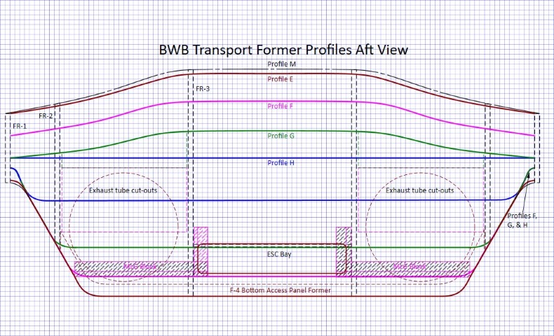
After having drawn up several different views using paper and pencil, I decided to try my hand at 2D Computer Aided Design. As of today, I have all fuselage profiles established; detailed layouts for both wings; a top, bottom, and side view of the fuselage; rib profiles; all now in digital 2D drawings. You can see these via the links to the left below.
Using the center fuselage front and aft profile views, I printed out templates for all the fuselage formers and fuselage ribs. I then took the templates and generated actual full size formers/ribs cut from 1/8 inch form core board.
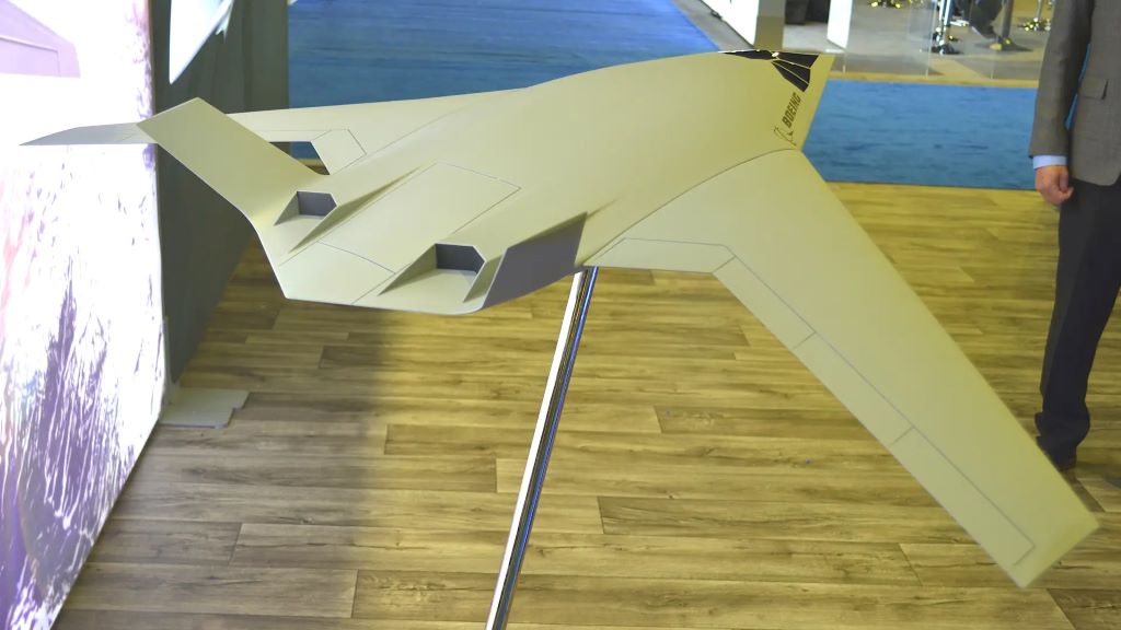
With the announcement on 13 October 2023 from the USAF that JetZero, an aerospace company based in the US, will build the world's first blended wing body (BWB) demonstrator aircraft (bottom image to the left) for the USAF, my design efforts to model the Boeing BWB have been placed on hold. Should I decide to try and model the JetZero BWB concept, updates will be posted on this webpage. More to come, maybe.
I will try and keep you up to date on my progress. For those of you that want to follow me through the process, I will post the date here for when the files below have changed.
(as of 5/3/2023)
BWB Scale Model Design and Build
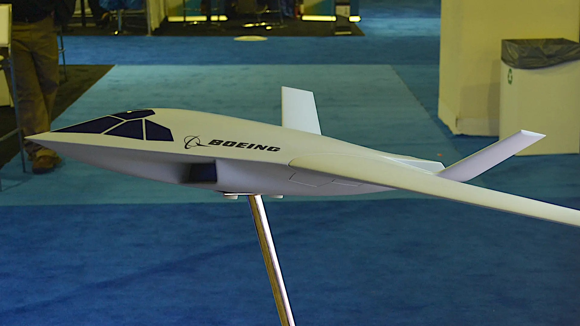
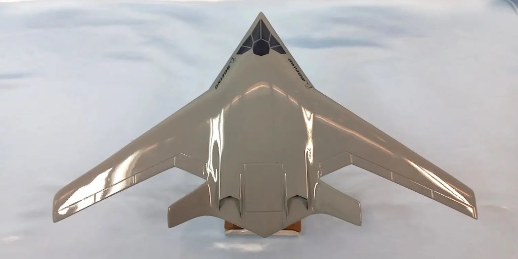
This build description is going to be somewhat different from others I produced in the past for my other scratch builds. First, this build is based only on a picture I ran across in a copy of Aviation Week and Space Technology (Feb 13-26, 2023) of a new concept from Boeing for a Blended Wing Body (BWB) military transport targeted for the US Air Force. This scalable configuration could be developed as a tactical airlifter Lockheed C-130 replacement, or a Boeing C-17 size strategic transport. The wingspan of the initial Boeing concept is estimated at about 130 feet, using medium or even high-bypass-ratio turbofans buried along the sides of the center fuselage. Second, there are no plans that I can download from the web for this build. Therefore, I will start this build description by working up the requirements of the RC model, and development of the plans to scratch build from. The first thing I needed to do was to see what additional data I could find on this new BWB transport, which I rapidly found was only a few more pictures. There is nothing in the way of any three views, line drawings, or specifications. Boeing currently is not releasing any additional data.
Using the top view picture I worked up my initial 'scale' representation of the BWB outline. Next, I broke out my old engineering design drawing kit (from my bachelors engineering class back in the mid-70's) and pulled out several scaled rules to find something that would provide me with a scale I could use to end up with a model in the 48-60 inch wingspan range. This wingspan range was set to be able to store the model in my workshop, and to carry it to the flying field in the bed of my Colorado pickup. What resulted was an initial plan that comes in with a 54-inch wingspan and a center fuselage of 13.5 inches wide by 30 inches long. So, this top view of the overall outline was put down on drawing paper as the starting point for my plans. Please read “My Design and Build Document” via the link in the section to the left for more of my design story.
 All HTML & CSS Coded by Larry
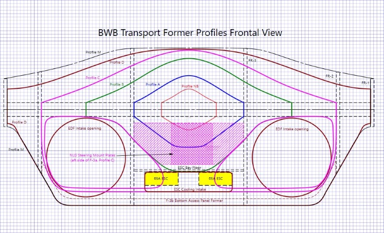
.jpg)