
For visitors to my website, my “Build of the Month” (BOTM) Series was created to help those who are trying to get started in building their own Radio Controlled (RC) Model Aircraft.
"Aerofred.com" and "Outerzone.co.uk" are two of my favorite web sites to obtain free RC model airplane plans for my new builds. Additionally, they like to post images of Builder's models, and both sites have posted my RC model images and build descriptions under the heading of the associated aircraft model. Other good sources for free plans are: "Hip Pocket Aeronautics Builders' Plan Gallery", "Vintage & Old-Timer RCM Free Plans", "James Hatton Blog Free Plans and Articles", "Hlsat Blog RCModeler Free Plans and Articles", and "Don Dewey Memorial RCM Plans Collection."
If you are currently not an active builder, and you would like to be, my BOTM Series is a great place to start. If you have an RC model aircraft that you would like to see featured in this section or feel others may find interesting, please let me know and I will make every attempt to find scratch build plans, photos, and maybe even a published build article, which I will then post in a future BOTM edition. Just send me an email @: Build of the Month.
Click on any link below to jump to that 2025 BOTM Edition
December 2025 — Westland P12 Wendover
November 2025 — Weekend Wren
October 2025 — X-100 INFINITY WING V2
September 2025 — RQ-4 Global Hawk
August 2025 — Andy Clancy's Stagger Bee
July 2025 — Aquabird
June 2025 — RCModeler's Small Wonder
May 2025 — Junkers Ju-87
April 2025 — Vought F4U Corsair
March 2025 — De Havilland DH 98 Mosquito
February 2025 — Supermarine Spitfire
January 2025 — Ilyushin IL-2 Stormovik
NOTE - You can view all images in a “Spotlight Box” by simply clicking on any image.
Build of the Month Series - December 2025 Edition
I hope you enjoyed last months BOTM Edition on the Weekend Wren. If you have an RC model that you would like to see featured in this section or feel others may find interesting, please let me know and I will make every attempt to find scratch build plans, photos, and maybe even a published build article, which will then post in a future edition. Just send me an email @: Build of the Month.
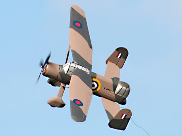
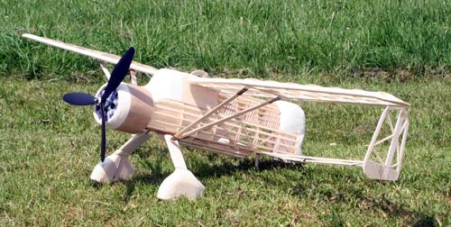
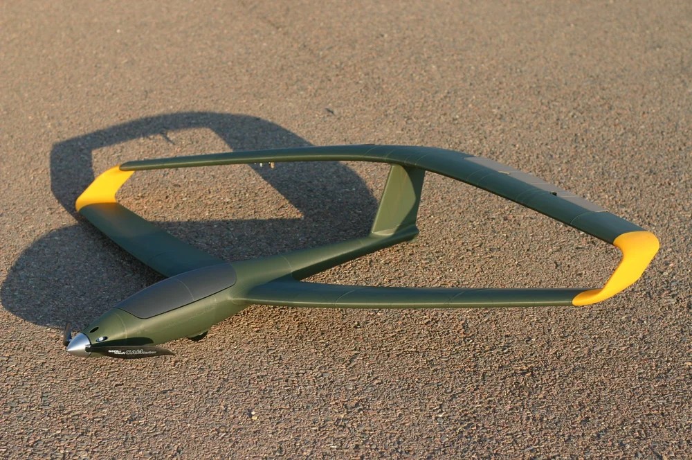
Ok, now lets see what I have for the month of December 2025. How about something similar to my “BOTM WW-II Mini-Series,” and in the European Theater. This time how about a fighter that is easily recognizable due to its unusual wing-tail configuration, and something most of you likely have never seen at the flying field. Given these requirements, this month features the “Westland P12 Wendover,” a prototype aircraft developed by the British during World War II.
Images Source: diseno-art.com.
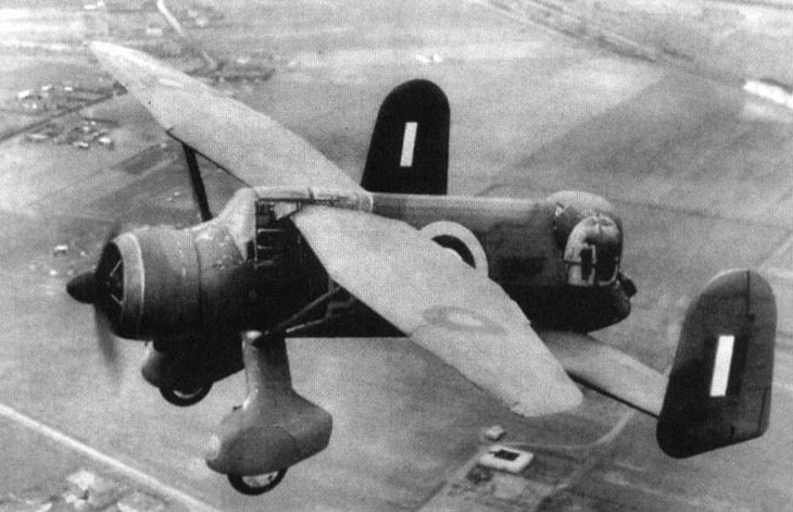
The Westland P12 Wendover was a prototype aircraft developed by the British during World War II. The aircraft was a development of the Westland Lysander, a workhorse aircraft used by the RAF for a variety of roles. The robust yet lightly armed Lysander was used for message delivery, picking up agents from behind enemy lines, artillery spotting, light bombing and supply dropping. However it was an outdated and slow aircraft which proved easy picking for enemy fighters. The loss rate for the aircraft was shocking, in just two months, May and June of 1940, 118 were lost over France or Belgium out of 175 deployed. After that summer the aircraft was moved back from frontline duty and more capable aircraft like the Curtiss Tomahawk and North American Mustang filled took its place.
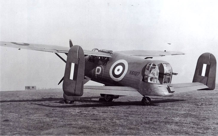
It was during this time that Westland tried to come up with a version of the aircraft which would be more capable in combat. The P12 Wendover was the result. The front half was more of less identical to the Lysander. However the rear half was heavily modified. The rear portion of the glazed cockpit was deleted, and the fuselage was modified to feature a twin tail unit and with a tandem wing configuration. The conventional tail was removed and in its place a power-operated 4-gun Nash & Thompson gunners turret was added. The Westland P12 Wendover was also fitted with a pair of 20mm cannons mounted above the wheel fairings for strafing runs.
The intended role of the aircraft was primarily as a ground-attack. It was during the German buildup and planned invasion of Britain that the aircraft was designed and tested. Its targets would have been the troop-carrying invasion barges and later columns of invading German soldiers. The P12 Wendover first flew on July 27, 1941. During test flights the pilot, Harold Penrose, reported that the aircraft handled well, with similar characteristics to the standard Lysander. The rudders were less effective at low speed, however it was easy to fly, steady and dives were described as remarkably smooth.
In the end the RAF decided not to order any production aircraft, and the project was abandoned in 1944 as its intended role became increasingly irrelevant, and the outdated design was surpassed by the far more advanced aircraft being brought into play during the later stages of the war.
- Actual Aircraft Specifications:
- Crew: Two
- Length: 8.41 m
- Wingspan: 15.24 m
- Height: 4.42 m
- Wing area: 13.9 m2
- Empty weight: 1,860 kg
- Max takeoff weight: 2,640 kg
- Power plant: 01 Bristol Perseus XII propeller engine with 80 horse thrust
- Propellers: 3-bladed constant-speed propeller
- Maximum speed: 360 km/hour
- Range: 800 km
- Service ceiling: 6,400 m
- Guns: 4 – 7.7mm Nash & Thomson machine guns in turret guns and 2 – 20mm cannons mounted above the wheel fairings
- Bombs: None
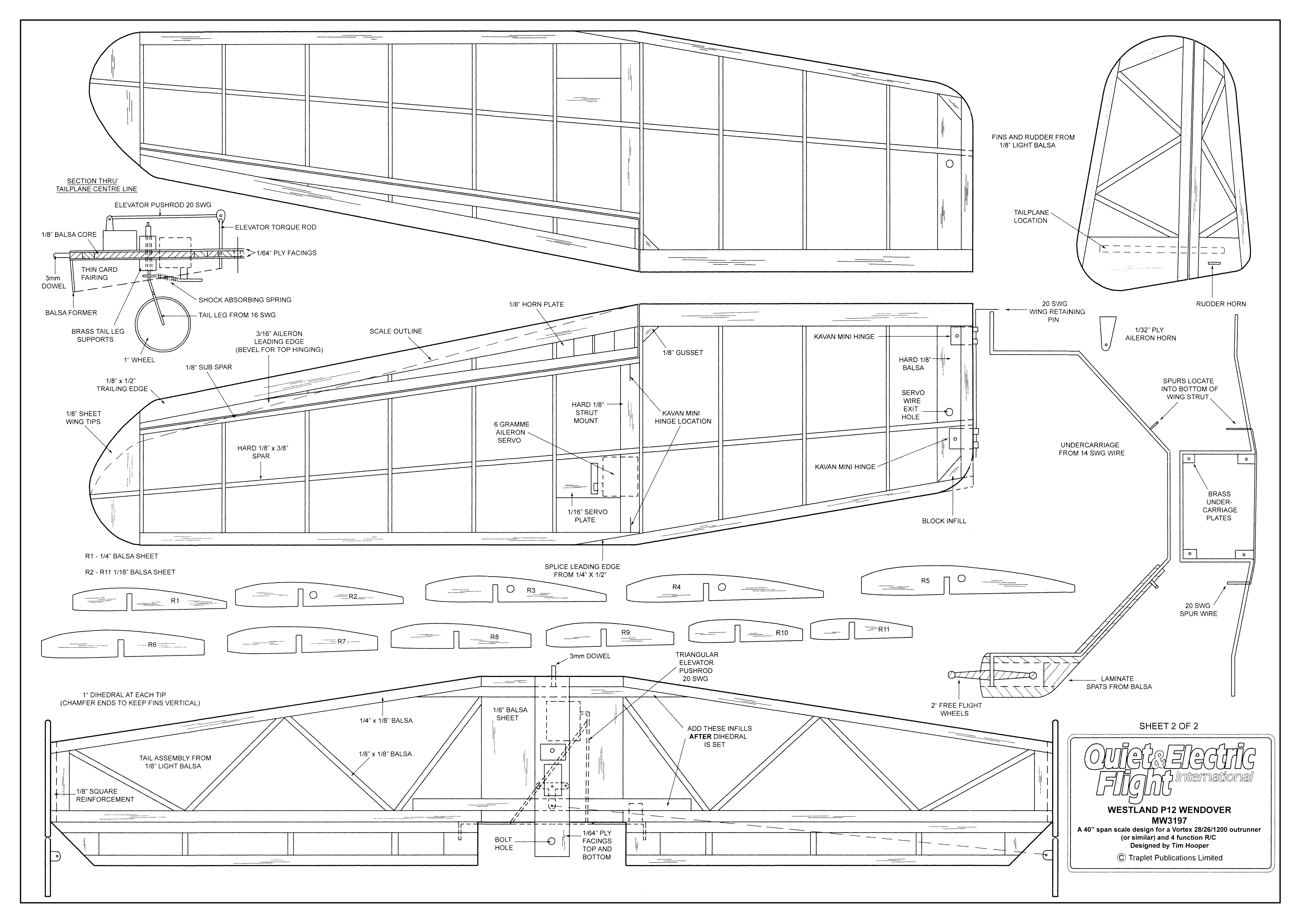
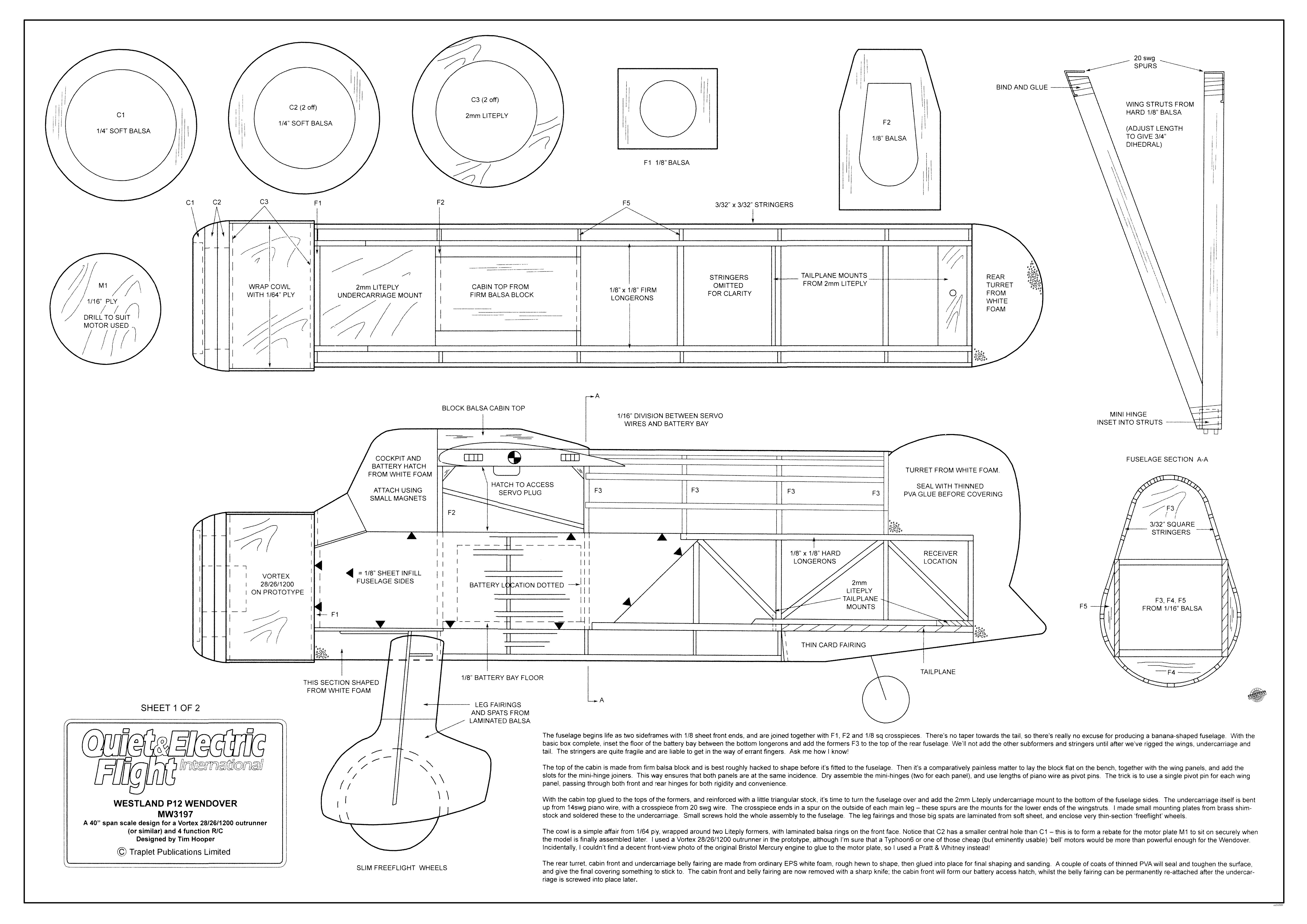
Images Source: Outerzone Westland P12 Wendover Webpage.
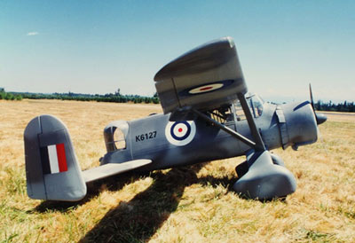
This months selection of the Westland P12 Wendover is based on a nice set of Traplet plans designed by Tim Hooper, and a January 2006 Quiet & Electric Flight International article, both of which are available for download @: Outerzone Westland P12 Wendover Webpage.
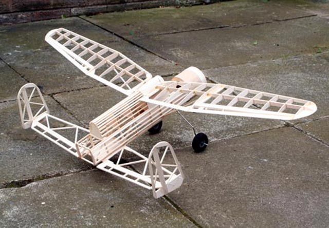
After looking over the plans, article and the build thread I can provide you with a few of my comments. As you will find for most WW-II fighter builds, this is not an RC model for someone just starting to learn how to do a scratch build. There are some quirks in the construction that need care in their execution; the incidence and overall rigging of the wings depends on the accurate fitting of mini-hinges in both fuselage and wing root and of the functional wing struts. And all those fuselage stringers are pretty delicate and won't tolerate rough handling, so be aware!.
The fuselage begins life as two side frames with 1/8″ sheet front ends, and are joined together with F1, F2 and 1/8″ sq crosspieces. There's no taper towards the tail, so there's really no excuse for producing a banana-shaped fuselage. With the basic box complete, inset the floor of the battery bay between the bottom longerons and add the formers F3 to the top of the rear fuselage. Do not add the other subformers and stringers until after you have rigged the wings, undercarriage and tail. The stringers are quite fragile and are liable to get in the way of errant fingers.
The top of the cabin is made from firm balsa block and is best roughly hacked to shape before it's fitted to the fuselage. Then it's a comparatively painless matter to lay the block flat on the bench, together with the wing panels, and add the slots for the mini-hinge joiners. This way ensures that both panels are at the same incidence. Dry assemble the mini-hinges (two for each panel), and use lengths of piano wire as pivot pins. The trick is to use a single pivot pin for each wing panel, passing through both front and rear hinges for both rigidity and convenience.
With the cabin top glued to the tops of the formers, and reinforced with a little triangular stock, it's time to turn the fuselage over and add the 2mm Liteply undercarriage mount to the bottom of the fuselage sides. The undercarriage itself is bent up from 14 gauge piano wire, with a crosspiece from 20 gauge wire. The crosspiece ends in a spur on the outside of each main leg — these spurs are the mounts for the lower ends of the wingstruts. Make small mounting plates from brass shim-stock and soldered these to the undercarriage. Small screws hold the whole assembly to the fuselage. The leg fairings and those big spats are laminated from soft sheet, and enclose very thin-section “freeflight” wheels.
The cowl is a simple affair from 1/64″ ply, wrapped around two Liteply formers, with laminated balsa rings on the front face. Notice that C2 has a smaller central hole than C1 — this is to form a rebate for the motor plate M1 to sit on securely when the model is finally assembled later. Tim used a Vortex 28/26/1200 outrunner in the prototype. Incidentally, Tim couldn't find a decent front-view photo of the original Bristol Mercury engine to glue to the motor plate, so he used a Pratt & Whitney instead!
The rear turret, cabin front and undercarriage belly fairing are made from ordinary EPS white foam, rough hewn to shape, then glued into place for final shaping and sanding. A couple of coats of thinned PVA will seal and toughen the surface, and give the final covering something to stick to. The cabin front and belly fairing are now removed with a sharp knife; the cabin front will form our battery access hatch, whilst the belly fairing can be permanently re-attached after the undercarriage is screwed into place later.
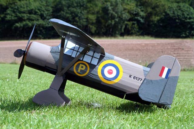
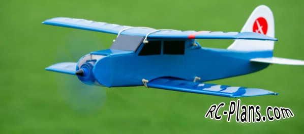
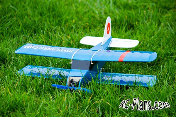
At the flying field Tim had his Wendover model airborne in around 20 feet and accelerating skywards. He was delighted to find that the model flew absolutely conventionally with no trace of pitch sensitivity at all. The rudders don't do a lot at low airspeeds, but at normal flight speeds they're pretty effective when used in
conjunction with the ailerons. A practical flying model of a little known, and very rare, unorthodox prototype from over 85 years ago. The little Wendy makes friends wherever she goes, and is a real attention getter, both in the pits and in the air.
- RC Model Specifications:
- Aircraft Type: Scale Warbird
- Wing Span: 40″
- Wing Chord: Varies from 5.2″ to 3″ Tip
- Total Wing and Horizontal Stabilizer Area: 234 square inches
- Wing Location: High Wing
- Airfoil: ClarkeY Section Flat Bottom
- Wing Platform: Double Taper
- Fuselage Length: 18.4″
- Stabilizer Span: 21.6″ with twin vertical stabs/rudders
- Number of Channels: 4 - Throttle, Ailerons, Rudder, Elevator
- Ready to Fly Weight: 20 oz. depending on power system selection
- Glow Fuel Engines: N/A
- Electric Powered: Output of 100-150 Watts, 20 Amp ESC, 2 cell LiPo pack of 1,500mah, and 9x7 3-blade prop.
The Westland P12 Wendover RC model in this months edition can be built using a set of plans and article available @: “Outerzone.”
Outerzone Westland P12 Wendover Webpage.
A Nice Westland P12 Wendover Build Thread with LOTS of Build Images.
I hope you have enjoyed this months selection, and just maybe, I have spurred some interest in trying your hand at building an RC model airplane.
Until next month - Keep the Balsa Dust Flying!!
Build of the Month Series - November 2025 Edition
I hope you enjoyed last months BOTM Edition on the X-100 Infinity Wing. If you have an RC model that you would like to see featured in this section or feel others may find interesting, please let me know and I will make every attempt to find scratch build plans, photos, and maybe even a published build article, which I will then post in a future edition. Just send me an email @: Build of the Month.
Ok, now lets see what I have for the month of November 2025. After two editions of 3D printed RC models, it is time to get back to the balsa and plywood builds again. How about something that is VERY easy to build, will not break the bank, is a biplane, and can be flown in a large back yard, a local ball park, or a small open field. Given these requirements, this month features the Weekend Wren, a mini RC model biplane designed by Tom Van Musteren and can be found @ Joyplanes.
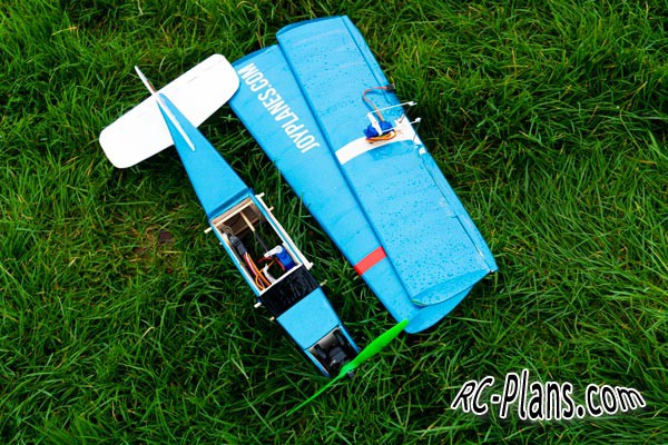

Images Source: RC-Plans Webpage.
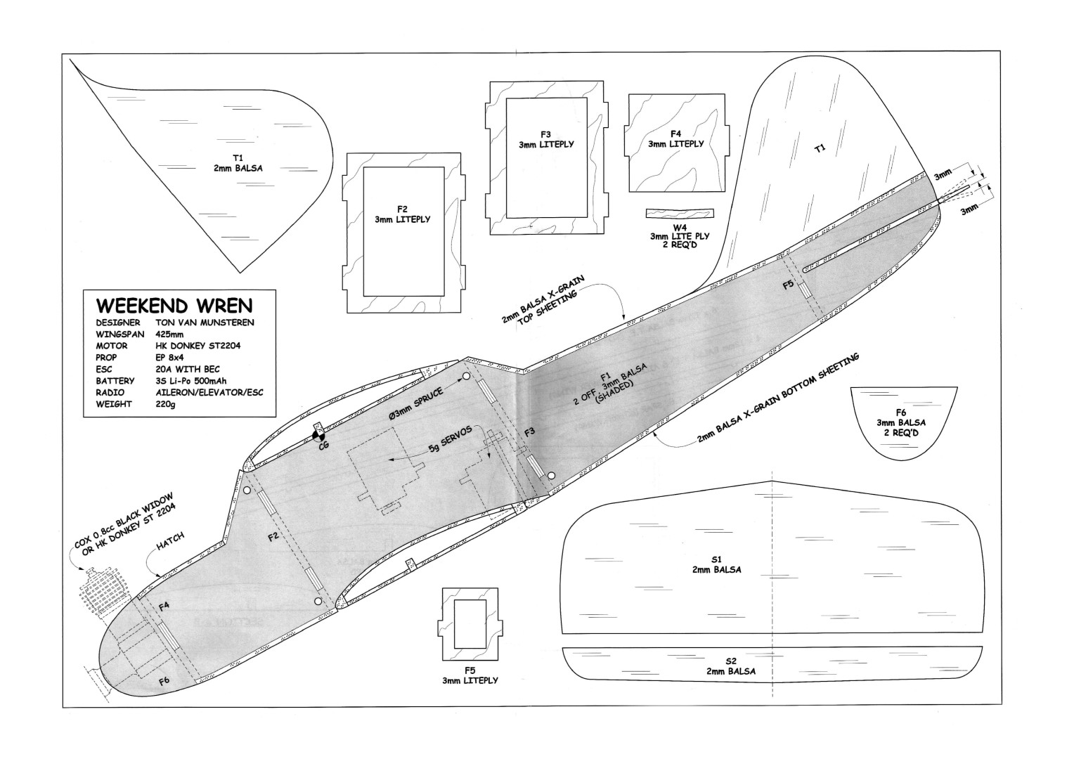
This RC model biplane is taken from a plan included in the April 2019 RCM&E magazine. The model is called “Weekend Wren” by Tom Van Musteren. A small RC model that looks like a project that will only take about a week of work, and with only 425mm of wingspan is almost a micro RC airplane.
This biplane is based on a German retro model called “Zaunkonig” that used a 0.8ccm Cox engine. A simple but great line for a mini biplane like this, the number of parts is simplified and with no rudder it is even simpler. Both wings are the same, except that the one below has small ailerons controlled by only one servo, another controls the elevator with a push rod.
- Weekend Wren RC Model Specifications:
- Aircraft Type: Mini-Biplane Park Flyer
- Wingspan: 425mm / 16.7″
- Wing chord: 108mm / 4.25″
- Overall Length: 377mm / 14.8″
- Height: 100mm / 3.9″
- Wing Area: 868cm² / 134.5in²
- Wing Loading: 8.5 oz/ft²
- Flight Performance Category: General Sport
- Center of Gravity Location: 33mm aft of top wing leading edge
- Flying Weight: 225g / 7.9 oz
- No. of Channels: 3 - Ailerons, elevator and motor (2 servos + 1 ESC)
- Control Movement: Ailerons and elevator - 3mm each way
- Motor: Brushless motor 2205 – 2300Kv or any similar motor, it works with a wide range
- ESC: Minimum of 15A or a recommended 30A w/UBEC
- Servos: 5g micro servos (x2)
- Rec. Props: Use the recommended propeller for the motor (8x4 prop)
- Battery: 3S 500 - 600 mah LiPo
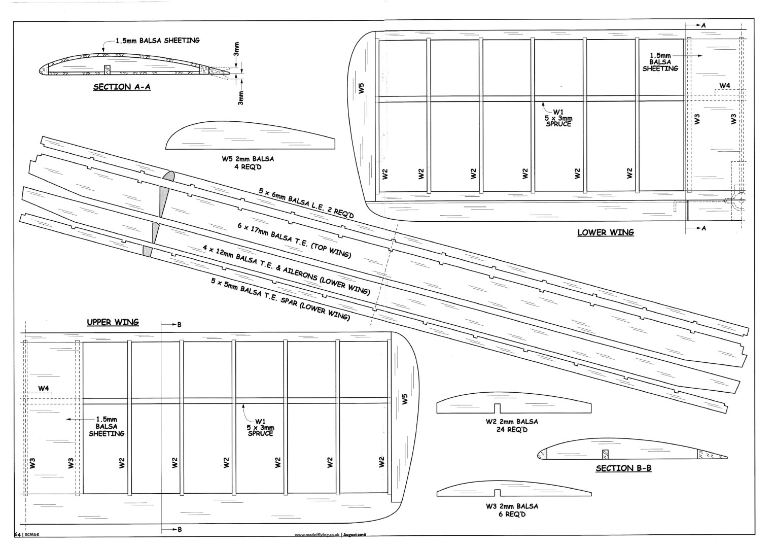
Plans for this little biplane can be downloaded from RC-Plans Website. A Complete Detailed Build Video is available @: Building the RC model airplane every body loved (YOU VOTED - I BUILT IT). You can also view flight video @: Balsa Wood Construction [Weekend Wren] | Maiden Flight.
Tools and Materials Needed:
- Balsa wood needed: 3 mm, 2 mm, 1.5 mm, a large sheet of each should be sufficient. Strips of balsa of 5X6 – 6X17 – 4×12, 5×5 mm
- Spruce or Basswood: 5x3mm for spars
- Plywood or Lite ply: 3 mm for the formers and spars
- Hardwood Dowel: 3 mm for the rubber band wing mounts
- Glues: CA or wood glue
- Rubber bands to strap the wings
- Bamboo Skewer for the elevator control rod
- Threaded Control Rods: 2-56 (x4)
- Elevator and aileron control rod linkages
- Ultracoat heat shrink covering (color of your choice)
- And your tools.
In Conclusion: It's a beautiful RC model aircraft, but I do not recommend it for beginners who are starting in aeromodeling, it is not that easy to build, although it is small, for someone who is just starting it can be a frustrating challenge. The flight handling characteristics are not very stable, requires a pilot with some experience in flight, plus the ailerons are too small and flying on a day with some wind is not recommended. But, if you already have some experience in RC model aircraft, this is a fun model aircraft, it takes at least a week of work (depending on the dedication you give it).
I hope you have enjoyed this months selection, and just maybe, I have spurred some interest in trying your hand at building an RC model airplane.
Until next month - Keep the Balsa Dust Flying!!!
Build of the Month Series - October 2025 Edition
I hope you enjoyed last months BOTM Edition on the RQ-4 Global Hawk. If you have an RC model that you would like to see featured in this section or feel others may find interesting, please let me know and I will make every attempt to find scratch build plans, photos, and maybe even a published build article, which I will then post in a future edition. Just send me an email @: Build of the Month.
Ok, now lets see what I have for the month of October 2025. Since I featured a 3D printable RC aircraft model last month, I figured I would share a very nice website and a very interesting 3D design with you in this BOTM Edition. Given these requirements, this month features the X-100 INFINITY WING V2, a 3D printable model designed by Eric and can be found on 3DAeroventures.
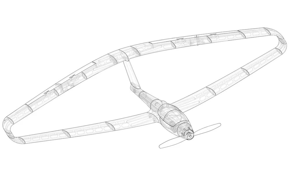
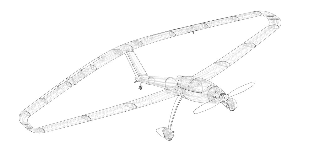
Images Source: X-100 INFINITY WING V2 Webpage.
The X-100 Infinity Wing is a 3DAeroventures original, designed by Eric Haddad, which features a very unique wing configuration that is rarely modeled and seldom seen in full-scale aircraft. Sometimes called a closed wing, joined wing or box wing, this configuration's unique wing tip design not only has structural benefits, but is expected to come with some aerodynamic advantages, namely the reduction of wingtip vortices. Wingtip vortices form a major component of wake turbulence and are associated with induced drag, which is a significant contributor to total drag in most aircraft. The previous sentence is just science-y aerodynamics talk for: “It flies really nice.”
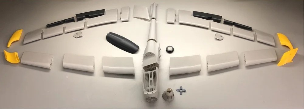
Quoting Eric — “The X-100 Infinity Wing has been re-designed into this V2 version to meet several goals: Improved stall performance, better printability/surface quality, increased part strength, the ability to print the parts in any material - PLA, ABS, ASA, PETG, and especially LW-PLA or LW-ASA, and much simpler slicing and the ability to use any slicer (like Prusa Slicer). I am now a big proponent of using multiple material types to build a good performing and long-lasting craft. So you should find this style of part design to be simpler to slice on your own and print in many different materials. The outer walls of the parts now print like a corrugated plastic - two single perimeter walls filled with a very low infill, anywhere between 3 - 7%. The downside is, printing this style of design in standard PLA leads to a heavier aircraft, though not too heavy to fly well. That's why I am particularly excited about the results I've got printing this aircraft as a hybrid with LW-PLA. I recommend at least printing some of the parts in LW-PLA to keep the weight as low as possible and for the ideal weight distribution. The hybrid version balances perfectly at the new recommended CG position with a 3S 2,200mah battery located in the middle of the battery compartment. A standard PLA version may require a larger battery or a small amount of nose weight to properly balance. If you do only print a few of the parts in LW-PLA I recommend printing the Back Wing parts in LW-PLA for better weight distribution.”
You should take a few minutes and view a video produced by Eric about his design of the original X-100 Infinity Wing, 3D printing and assembly, and some funny moments during his first flight attempt. This can be viewed @: 3D Printed Infinity Wing RC Airplane! Another great video produced by Eric about his redesign efforts and 3D modeling of the X-100 can be viewed @: The Infinity Wing 3D Printed Aircraft Gets an Upgrade! And finally, another very nice X-100 3D printing and build video produced by Troy McMillan with lots of 3D printing pointers can be viewed @: 50" RC Flying Wing Full Step by Step Build Instructions.
- X-100 INFINITY WING V2 Model Specifications:
- Aircraft Type: Flying Wing
- Wingspan: 1,270mm / 50″
- Length: 879mm / 34.6″
- Height: 242.5mm / 9.5″
- Wing Area: 437.5 in²
- Wing Loading (LW-PLA Hybrid): 13.3 oz/ft²
- Wing Loading (PLA): 17.6 oz/ft²
- Flight Performance Category: General Sport and Scale Aerobatics
- Center of Gravity Location: 45mm in Front of Trailing Edge at the Wing Root
- Weight of Printed Parts (LW-PLA Hybrid): 684g / 24.1 oz
- Weight of Printed Parts (PLA): 1,048g / 37 oz
- Flying Weight (3S 2200 mAh): 1,130g (LW-PLA) to 1,520g (PLA) / 39.9 - 53.6 oz
- Recommended Max Flying Weight: 1,800g / 63.5 oz
- No. of Channels: 4 - Throttle, Aileron/Elevator (Elevons), and Rudder (for Upgraded Version only)
- Servos: EMAX ES08MA II (12g) Metal Gear Servo or equivalent 23x11.5x24mm size servo
- Motor Options: EFlite Power or 15 Leopard 3536-7T 1100kV; or motor with equivalent X mounting pattern
- ESC: 50A ESC like HobbyWing Skywalker Series 50A ESC
- Rec. Props: 12x8(EFlite) or 11x6 (Leopard) Folding Propeller; or 10x6 to 11x7 Propeller for landing gear version (do not use a prop larger than 11” for proper ground clearance)
- Battery: 3S 2,200 mAh LiPo or 4S 2,200 - 3,300 mAh
All the required STL files can be downloaded for free from the X-100 INFINITY WING V2 Webpage. Included in the download are — X-100 V2 STL Files (total of 48); Simplify3D Factory Files (individual parts and grouped builds); Cura and PrusaSlicer Profiles; Recommended Slicer Settings for Different Materials (Excel and PDF format); Generic Gcode for i3 style printers; X-100 Wing Dolly files; and a X-100 Infinity Wing V2 3D Printed R/C Aircraft Build Guide.
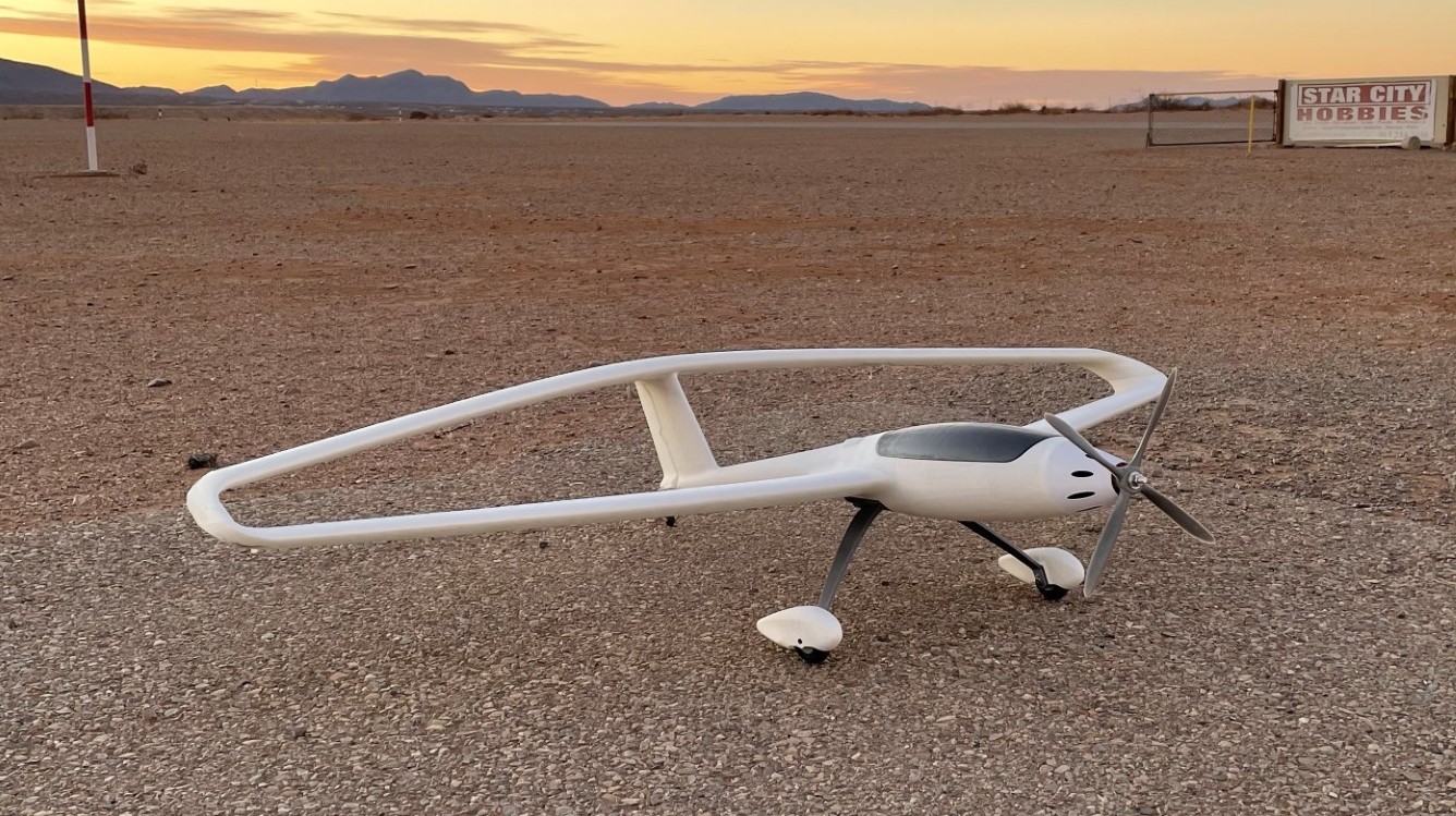
You can also download the X-100 INFINITY WING landing gear and rudder upgrade. This free upgrade kit is compatible with the X-100 Infinity Wing V2 file set. It carries the Infinity Wing design to a whole new level with a new fuselage design complete with landing gear and rudder capability.
Images Source: X-100 INFINITY WING V2 Webpage.
The Minimum requirements for successfully printing 3DAeroventures designs are:
- 3D Printer with 200mm x 200mm x 205mm Print Bed Size
- 0.4mm Nozzle
- Heated Bed (recommended)
- Any Slicer Software
- Lightweight PLA like ColorFabb LW-PLA, OVERTURE Air PLA, Polymaker LW-PLA, or Polylight 1.0
- High quality PLA like Creality Hyper-PLA or Paramount3D (feel free to test other materials like PETG, PC, ABS, ASA, etc.)
Tools and Materials Needed:
- PETG, ABS, ASA, or PC for motor mount
- TPU or TPE for Belly Wheel Tire, or MLG Tires for Landing Gear Upgrade
- Medium Bodied CA/Super Glue
- Accelerator for CA
- Sandpaper and/or Small Files
- Soldering Iron (for heat set threaded inserts)
- Screwdriver and/or allen wrench for chosen screws/bolts
Hardware Needed:
Fuselage:
- M3 x 0.5mm Thread Heat-set Threaded Inserts for wing bolts (x8)
- M3 x 0.5mm Thread Lock Nuts for motor mount (x4)
- M3 x 0.5mm Thread x 15mm (or 30mm) Long Socket Head Screws for motor mount (x4)
- 5mm O.D x 3mm Thick Rare Earth Magnets for Removable Canopy (x4)
- 3mm O.D. Carbon Fiber rod or equivalent O.D. wood or plastic dowel for wheel axles (x2)
- M2 or #2 Thread Forming or Tapping Screws for mounting cowl (x4) (spare servo mounting screws will work)
Wings:
- M3 x 0.5mm Thread Heat-set Threaded Inserts for wing tip bolts (x4)
- M3 x 0.5mm Thread x 10mm Long Socket Head Screws for removable wings (x12)
- M2 or #2 Thread Forming or Tapping Screws for mounting servo covers (x8)
- 6mm O.D. x 4mm I.D. (or 0.150” I.D.) x 600mm long carbon fiber hollow tubes for wing spars cut to these lengths:
- 300mm Long (x3)
- 200mm Long (x1)
- 1mm - 1.5mm O.D. x 400mm long carbon fiber rod or steel wire for elevon hinges (x2)
- 1.2 mm steel wire for servo control rods (x2)
Landing Gear and Rudder Upgrade:
1 additional EMAX ES08MA II (12g) Metal Gear Servo or equivalent 23x11.5x24mm size servo for rudder
- M3 x 0.5mm Thread x 15mm Long Socket Head Screws for landing gear mount (x5)
- M3 x 0.5mm Thread Lock Nuts for main tires (x4)
- M3 x 0.5mm Thread x 30mm Long Socket Head Screws for main tires (x2)
- Wheel collars to fit 1.5mm - 2mm steel wire for tailwheel (x2)
- 1mm O.D. x 10mm Long Pins cut from scrap carbon fiber rod for wheel pants (x8)
- 1mm - 1.5mm O.D. x 150mm Long Carbon Fiber rod or Steel Wire for Rudder Hinge
- 1.8mm - 2mm steel wire for tailwheel
- 1.2mm - 1.5mm steel wire for rudder servo control rod
- Pushrod Connector Linkage for Rudder Servo
The X-100 Infinity Wing 3D model is easy to hand launch and it flies like any Sport or Scale Aerobatics model. It looks super cool in the air due to it's unique wing design. You can view it flying in two videos @: X-100 Infinity Wing Flight Footage, and X-100 Infinity Wing Maiden.
I hope you have enjoyed this months selection, and just maybe, I have spurred some interest in trying your hand at building an RC model airplane.
Until next month - Keep that 3D Printer Printing!!
Build of the Month Series - September 2025 Edition
I hope you enjoyed last months BOTM Edition on the Stagger Bee. If you have an RC model that you would like to see featured in this section or feel others may find interesting, please let me know and I will make every attempt to find scratch build plans, photos, and maybe even a published build article, which I will then post in a future edition. Just send me an email @: Build of the Month.
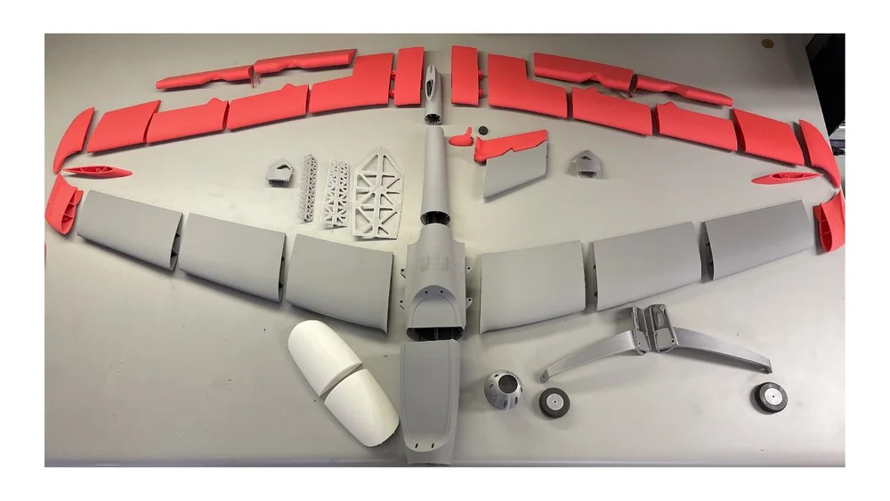
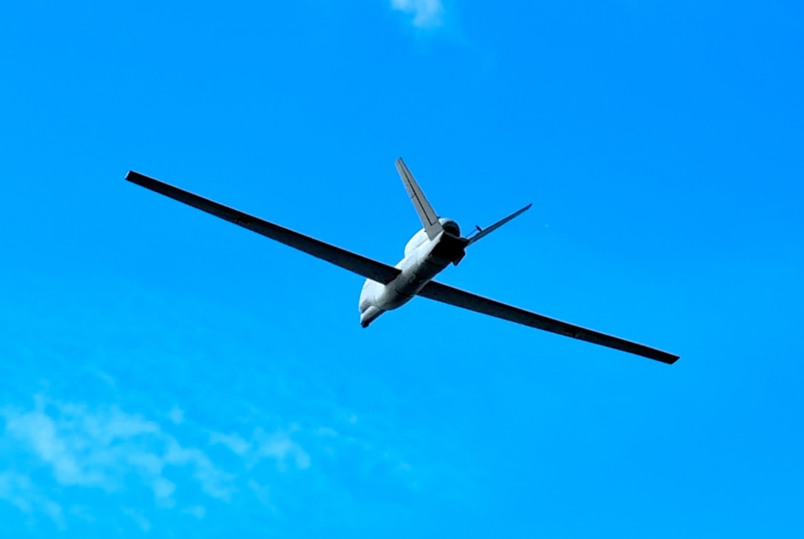
Ok, now lets see what I have for the month of September 2025. I though I would try something completely different this month. With the introduction of the 3D Modeling & Printing Page to my website, lets see about looking into the world of 3D RC model airplane building. Given this requirement, this month features the RQ-4 Global Hawk, in a 3D printable RC model designed by ptikyle and can be found on Cults3d.com.
Images Source: Cults3d.com.
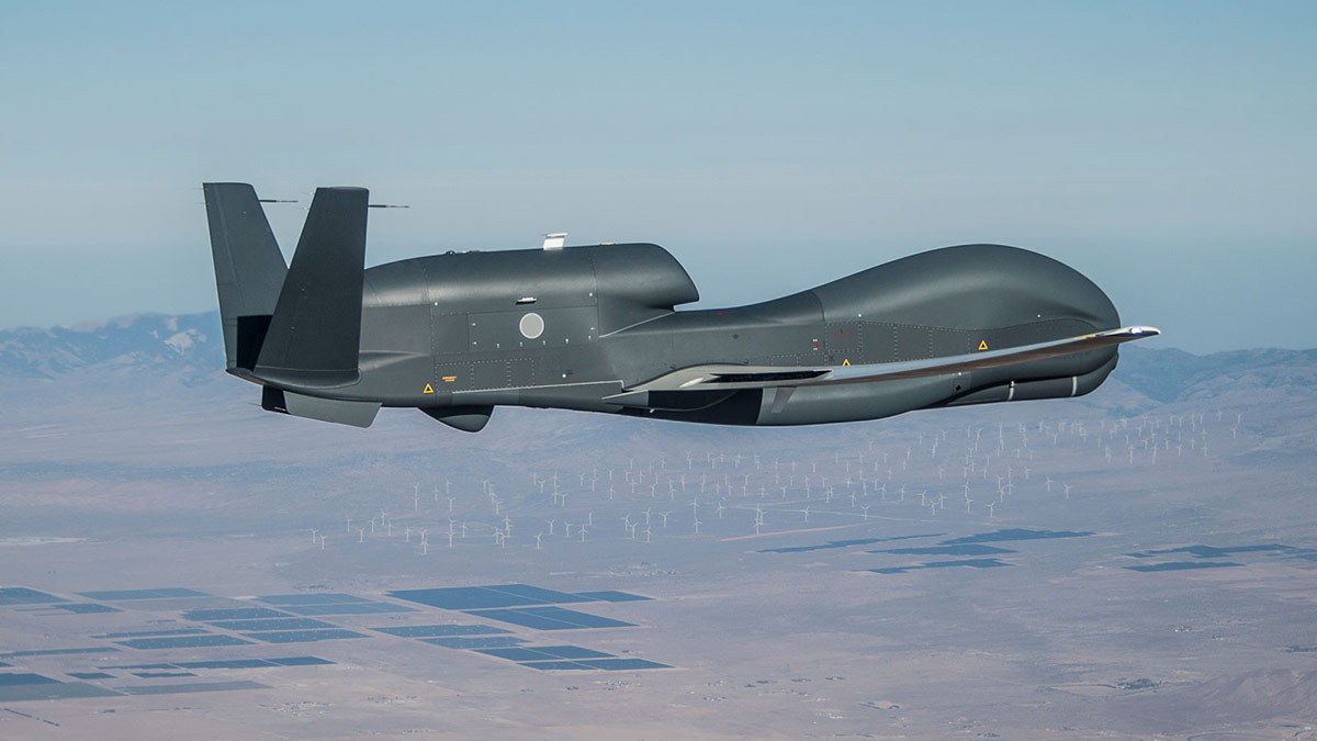
The RQ-4 Global Hawk is a high-altitude, long-endurance, remotely piloted aircraft with an integrated sensor suite that provides global all-weather, day or night intelligence, surveillance and reconnaissance (ISR) capability. Global Hawk's mission is to provide a broad spectrum of ISR collection capability to support joint combatant forces in worldwide peacetime, contingency and wartime operations. The Global Hawk provides persistent near-real-time coverage using imagery intelligence (IMINT), signals intelligence (SIGINT) and moving target indicator (MTI) sensors.
Global Hawk is flown by a Launch and Recovery Element (LRE) and a Mission Control Element (MCE). The LRE is located at the aircraft base and functions to launch and recover the aircraft while en route to and from the target area. The MCE controls the Global Hawk for the bulk of the ISR mission. Like the LRE, the MCE is manned by one pilot, but adds a sensor operator to the crew. Command and control data links enable complete dynamic control of the aircraft. The pilot workstations in the MCE and LRE are the control and display interface (cockpit) providing aircraft health and status, sensors status and a means to alter the navigational track of the aircraft. From this station, the pilot also communicates with outside entities to coordinate the mission (air traffic control, airborne controllers, ground controllers, other ISR assets).
Current Operational Capabilities and Variants
Dimensions: Wingspan ~130.9 feet (39.9 meters), length ~47.6 feet (14.5 meters), height ~15.3 feet (4.7 meters)
The wing area is ≈540 ft², giving a very high lift-to-drag ratio (≈33:1) at altitude
Weight & Payload: Typical empty weight ~15,000 pounds (6,804 kilograms); maximum gross takeoff ~32,250 pounds (14,628 kilograms)
Internal capacity ~3,000 pounds (1,360 kilograms) on RQ-4B, though early (Block 10) NASA/AAF versions carried about half
There are hardpoints (up to ~1,000 pounds/453,5 kilograms each) under the wings for additional external payloads
Performance: Cruise speed is about 310 knots (357 miles/570 kilometers per hour); max about 340 knots (391 miles/630 kilometers per hour). Service ceiling is about 60,000 feet (18,000 meters), with demonstrated loiter altitudes up to 65,000 feet (19,812 meters)
Range/Endurance: Ferry range 12,300 to 14,200 nautical miles; typical missions 11,000+ nautical miles with 30–34+ hour endurance.
In 2014 a Block-40 Global Hawk flew 34.3 hours, an unrefueled USAF record.
Powerplant: 1× Rolls-Royce AE 3007H turbofan (military designation F137) producing ~7,500–7,600 lbf thrust
A secondary generator system doubles electrical power for avionics.
Sensors: RQ-4 is an imaging and signals ISR platform. Block 30 carries a multi-int sensor suite (electro-optical/IR camera, Raytheon synthetic-aperture radar, and high/low-band SIGINT pods)
A universal adapter even allows U-2 sensors (MS-117, SYERS II) to fly on early RQ-4Bs.
Block 40 upgrades replace EO with the MP-RTIP AESA ground-surveillance radar for GMTI (moving-target indicator) and SAR.
(Earlier Block 20 aircraft had only electro-optical imagery.) Data links include wideband SATCOM (Ku-band 48″ antenna) and LOS links (X-band and UHF), enabling real-time imagery downlink to global ground stations.
Operators: Beale AFB, Edwards AFB, Grand Forks AFB, Andersen AFB, NAS Sigonella, Yokota AB
Other Operators: US Navy (RQ-4N/MQ-4C Triton), NATO's Alliance Ground Surveillance Program (5 ea. RQ-4B Block 40s), Japan (3 ea. RQ-4Bs), South Korea (4 ea. RQ-4Bs)
I picked the RQ-4 3D model for a couple reasons. First, in keeping with models for newcomers to RC model building and flying, I wanted a model that would be simple to build and easy to fly. Second, I worked on the USAF Global Hawk program for six years as a flight test manager and a Air Vehicle IPT program manager, and will most likely end up printing one of these out for myself.
- RQ-4 3D Model Specifications:
- Aircraft Type: Powered Glider
- Wing Span: 1,700mm
- Airfoil: Flat Bottom
- Wing Platform: Full-cantilever, Double Tapered, Variable Chord
- Fuselage Length: 882mm
- Fuselage Width: Varies
- Rec. No. of Channels: 4 - Throttle, Flaperons, and V-tail Ruddervators
- Landing Gear: None
- Weight w/o LiPo: 937 grams depending on power system selection
- Electric Powered: Recommended Electric Ducted Fan 50mm min., 4000KV (4S); 5000KV (3S), LiPo tested 4S 2300mah - 2600mah
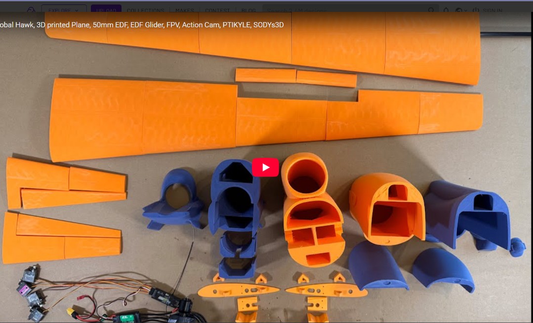
The 3D build of this model is easy enough for even me. All the required STL files (a total of 46 of them) can be purchased and downloaded from Cult3D.com for under $20. You should take the time to view Bill's 24 minute build video at: RQ-4 3D Model Build Video. For 3D printer filament material, you will need active foaming LW-PLA, PLA/PETG, and TPU filaments. Ptikyle recommended to use 3-4% grid infill for the wings and all other LW-PLA parts.
I contacted Creality about using LW-PLA with my Ender-3 V3 and they responded with the following: “Yes, the Ender-3 V3 is compatible with 1.75mm Polymaker Light Weight PLA (LW-PLA) and eSUN LW-PLA filaments. However, please note that Light Weight PLA foams and expands when printed, so it requires special print settings, such as:
Lower printing temperature (typically around 190–230°C depending on brand)
Lower flow rate (usually between 40–60%)
Higher printing speeds to optimize the foaming effect
Direct Drive setup recommended (optional but beneficial)
Please refer to the filament manufacturer’s guidelines for the best settings, and consider doing a few test prints to fine-tune for optimal results.”
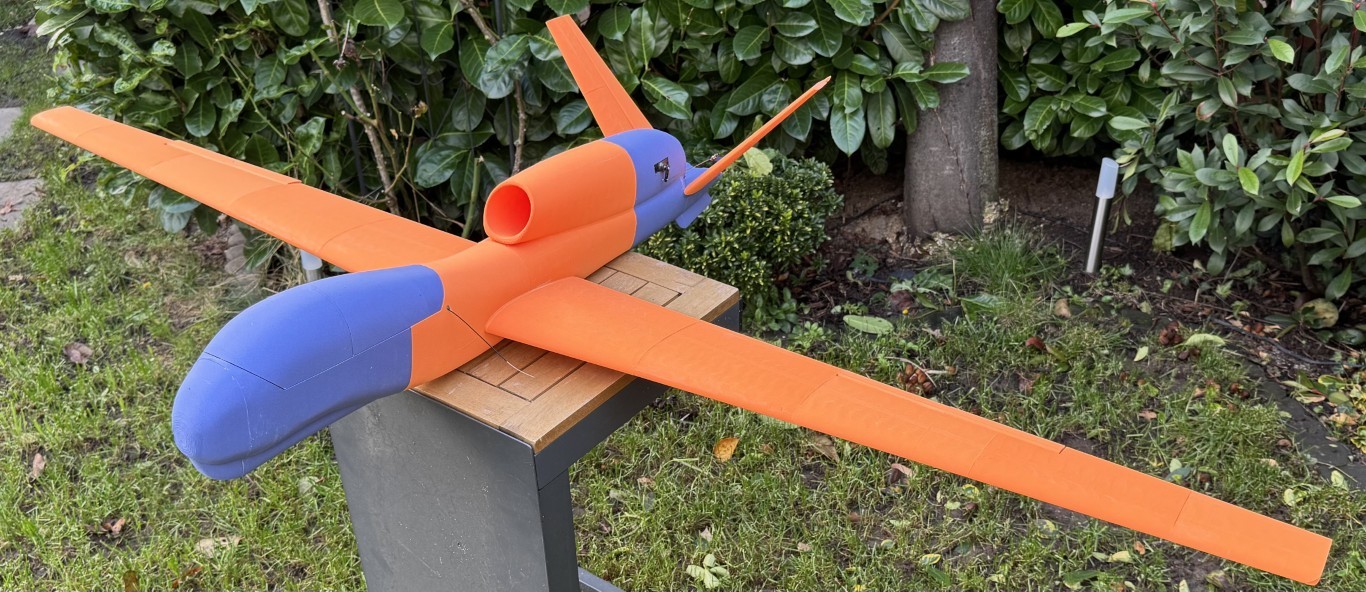
The model can be built with a First Person View (FPV) Nose DJI O3 or similar, Action Cam Nose, or make your own FPV-Nose! Wings are removable for transport! Other hardware and material you will need for your build includes:
2 Carbon Fiber Tubes 8x800mm
1 Carbon Fiber Tube 8x400mm
2 Carbon Fiber Rods 2x98mm
2 Steel Wire 1.5x130mm
2 Steel Wire 1.5x40mm
4 Machine Screws M3x10 and 4M3 Nut
Servo Extension Cables: 2x500mm, 2x400mm, 1x200mm
4 each 9g Metal Gear Servos
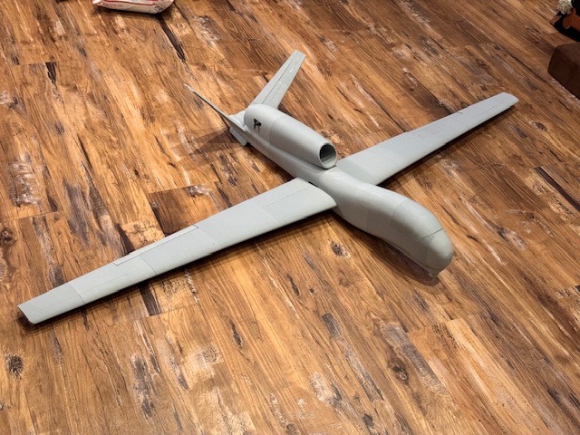
This 3D model RQ-4 is easy to hand launch and it flies like a powered glider. Zero bad tendencies. It looks super menacing when its in the air. You can view it flying in two videos at: Bill's First Good Flight, and Thomas's First Flight.
Cults3d.com RQ-4 Global Hawk Webpage
I hope you have enjoyed this months selection, and just maybe, I have spurred some interest in trying your hand at building an RC model airplane.
Until next month - Keep that 3D Printer Printing!!
Build of the Month Series - August 2025 Edition
I hope you enjoyed last months BOTM Edition on the Aquabird RC model. If you have an RC model that you would like to see featured in this section or feel others may find interesting, please let me know and I will make every attempt to find scratch build plans, photos, and maybe even a published build article, which I will then post in a future edition. Just send me an email @: Build of the Month.
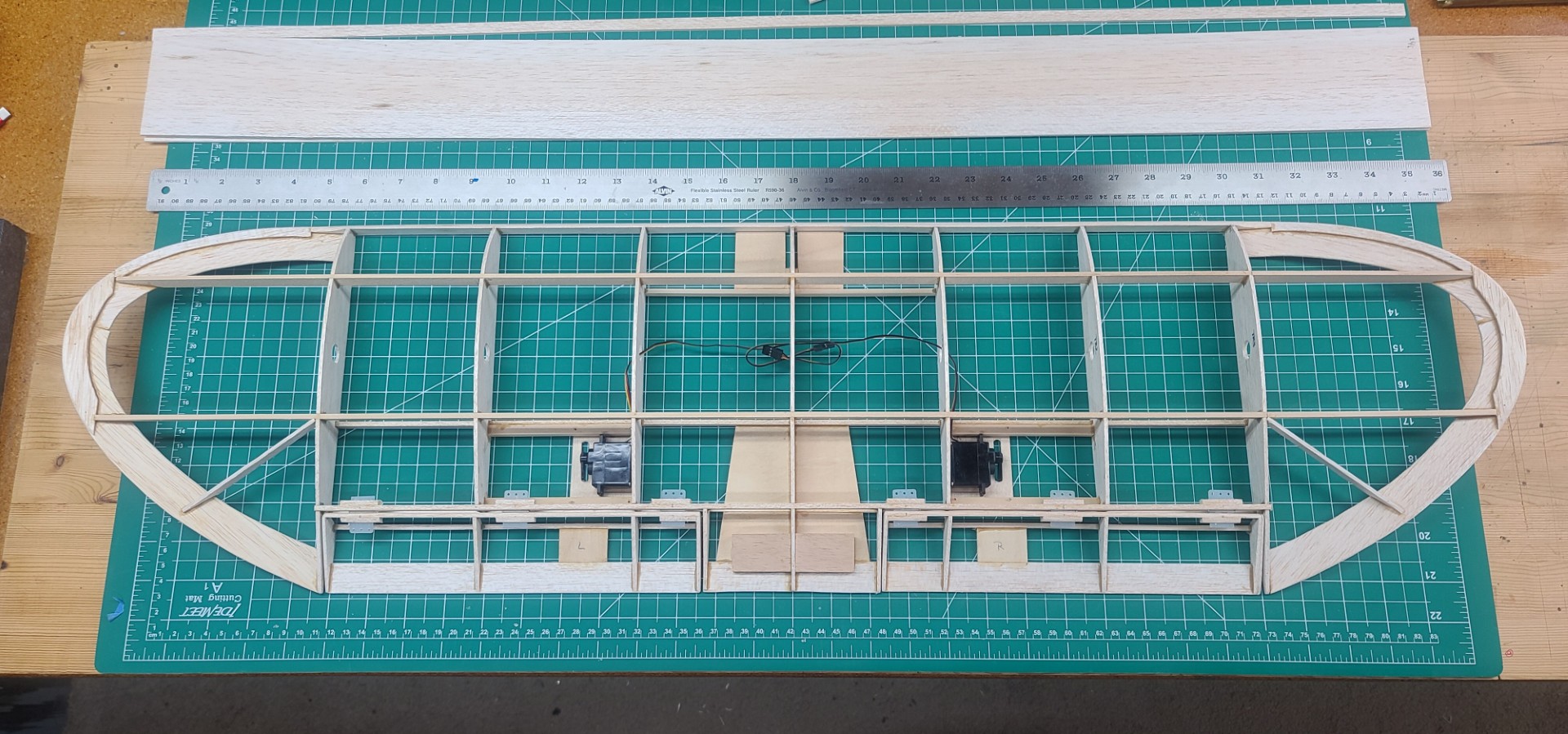
Ok, now lets see what I have for the month of August 2025, which also just happens to be the Two Year Anniversary Edition. Looking back through my previous BOTM Series Editions, I could only find one biplane in the total mix. Lets see about something that is easy to build, fun to fly, is economical, and is a biplane. Given these requirements, this month features the Stagger Bee, another classic design from Clancy Aviation. This selection is also appropriate in that my first edition of the BOTM Series was an Andy Clancy design, his Speedy Bee.
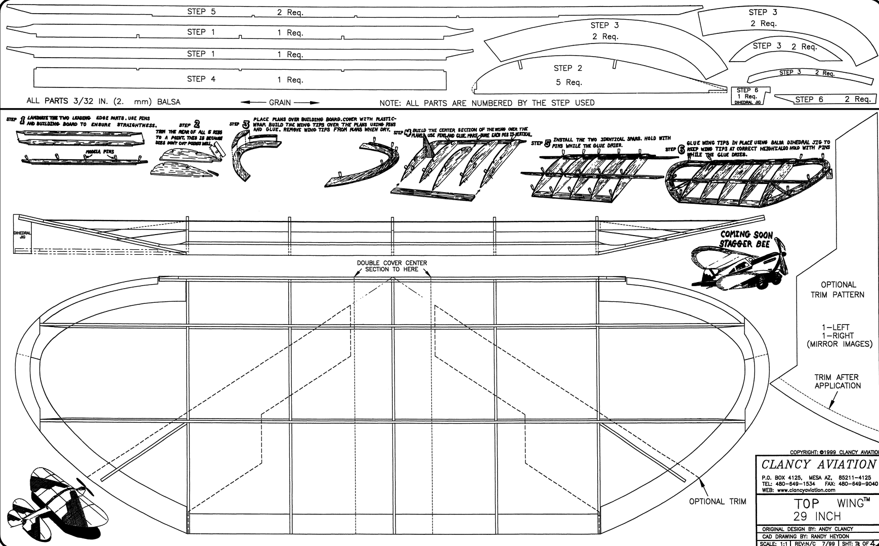
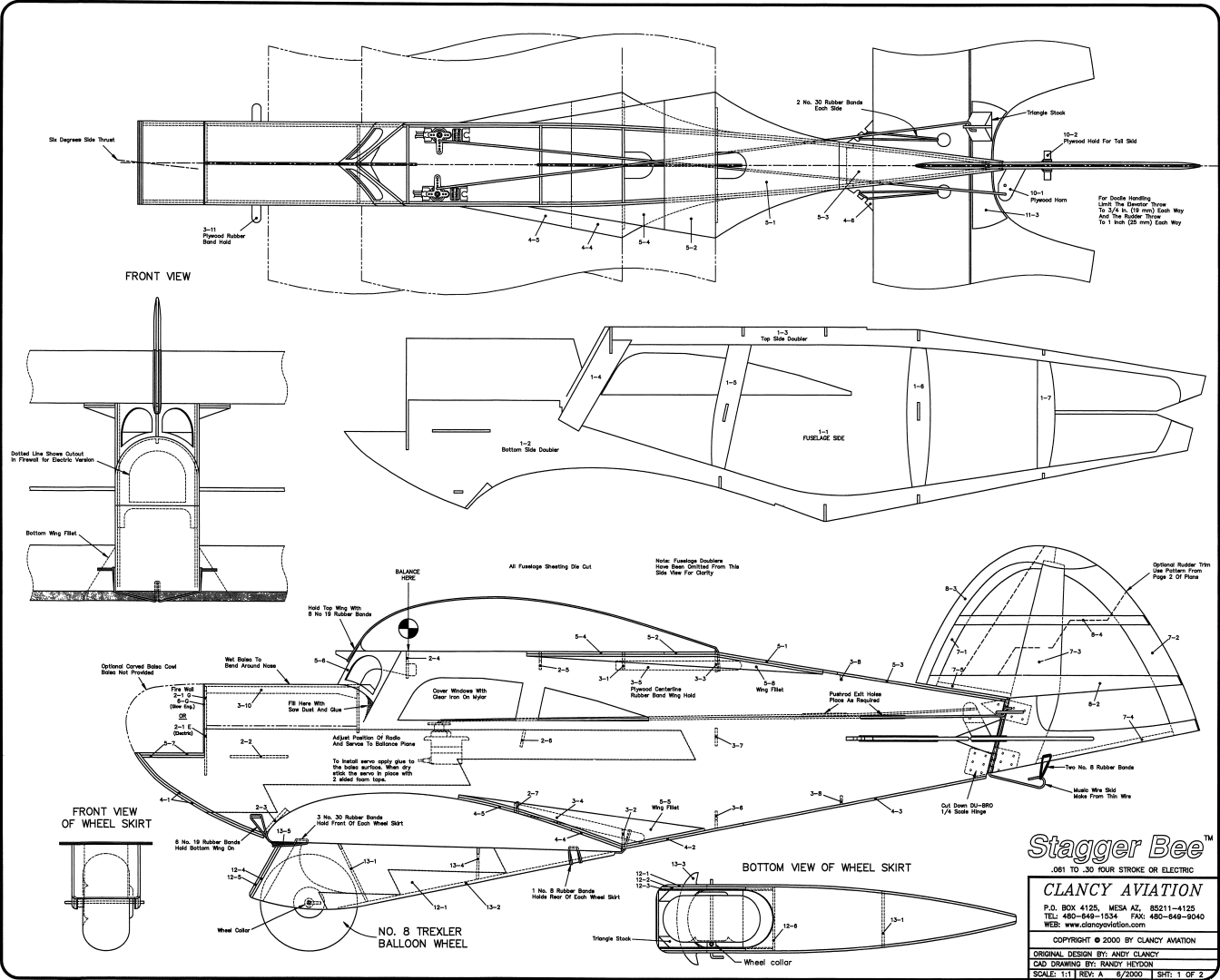

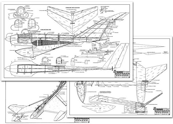
Plan Images Source: Extracted from Clancy Aviation Stagger Bee Plans.
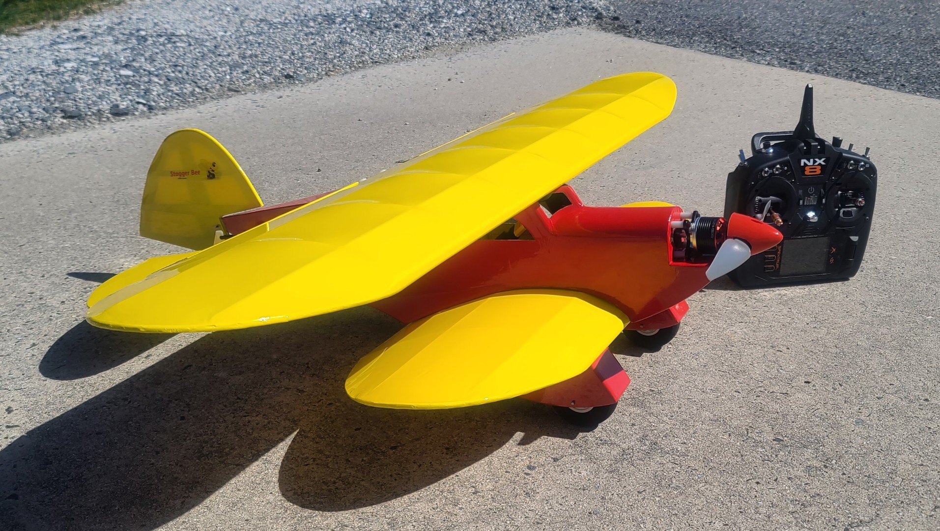
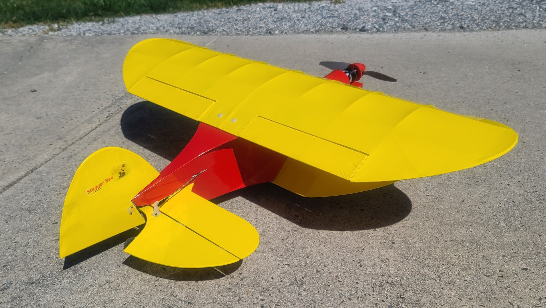
The inspiration for the Stagger Bee comes from the Stits SA-2A Sky Baby and the Beechcraft Stagger-wing. The Stagger Bee captures the special classic grace of a Stagger-wing Beechcraft. The original design is a fun 29″ top and 24″ bottom wingspan three channel sport biplane, which is still very much a Bee. You know: Oversized control surfaces, hands-off stability, extremely low minimum flying speed, and easy aerobatics. The Stagger Bee is just a Bee that is a biplane. It can manage having more power than a Lazy Bee.
Clancy's Stagger Bee is designed to fly with glow engines as small as a .061, and strong enough to manage larger engines up to .15 sport two-cycles or even up to .30 four-cycles. With larger engines it will have vertical capabilities. An electric-powered Stagger Bee typically will have a total flying weight of around 30 to 40 ounces ready to fly. It is recommended you use motors with a power output of 250 - 600 watts. The electric Stagger Bee tends to be tail heavy with brushless motors. You might want to use an oversize motor to help balance the plane even though you do not need the extra power. Larger motors can be detuned by throttling them down, or by using a smaller prop than specified for the motor, or by not using the maximum number of cells. The best battery size to use is a 3-cell LiPo pack up to 4,000 mah. Be sure to decide on the power plant and other options before you cut and glue the first balsa piece!
I found a good Stagger Bee build log that lists several modifications needed, which I used in my Stagger Bee scratch build. You can find this build log on the RC Groups website. You can download Andy Clancy Aviation Stagger Bee plans, assembly manual, and an RCM review from Aerofred.com or Outerzone.co.uk. Websites using the links I have provided below.
Andy Clancy likes to make his planes “crash proof” by using lots of elastic rubber bands. According to his plans and instructions, the wings, stab/elevator, and main landing gear (MLG) skirts are all held in place that way. I prefer to epoxy the stab/elevator into the fuselage, and use bolt-on wings and MLG skirts, so I did my Speedy Bee scratch build that way.
- Stagger Bee Model Specifications:
- Aircraft Type: Sport Biplane
- Wing Span: 29.6″ top and 24.2″ bottom
- Wing Chord: 10″
- Total Wing Area: 465 sq. in. (Top – 260 sq. in.; Bottom – 205 sq. in.)
- Wing Location: Negative-stagger on Top & Bottom of Fuselage
- Airfoil: Flat Bottom
- Wing Platform: Full-cantilever, Constant Chord w/Extra Large Rounded Wingtips
- Dihedral @ each Wingtip: 1.3″
- Fuselage Length: 24.4″
- Fuselage Width: 2.35″
- Horizontal Stabilizer Span: 18.5″
- Horizontal Stabilizer Chord: 6.25″
- Horizontal Stabilizer Area: 86.3 sq. in.″
- Stab Airfoil Section: Flat
- Vertical Stab/Rudder Height: 6.5″
- Vertical Stab/Rudder Area: 30.6 sq. in.
- Rec. No. of Channels: 3 - Throttle, Rudder, and Elevator
- Fuel Tank Size: 4 oz.
- Landing Gear: Conventional Tail Dragger
- Ready to Fly Weight: 36 - 40 oz. depending on power system selection
- Glow Fuel Engines: from .061-.15 two-stroke or up to .30 four-stroke
- Electric Powered: Output of 250 - 600 watts, equivalent ESC, 3-cell LiPo pack sized up to 4,000 mah.
A scratch build of the Stagger Bee is straight forward. All of the required parts can be made from templates which are detailed in the plan sheets. Andy provides very clear assembly steps in his manual for the fuselage, tail feathers and wheel skirts, and directly on the plan sheets for both wings. With a little prior building experience, your build should go smoothly and quickly.
As I mentioned earlier, for my Speedy Bee scratch build I made several modifications to the design and plans. This includes extension of the top wing to 37″ with addition of flaperons, and a steerable tailwheel assembly. All of the modifications are covered in great detail with many build images in my Stagger Bee Build Description, so I will not duplicate those here.
AeroFred Stagger Bee Webpage
Outerzone Stagger Bee Webpage
I hope you have enjoyed this months selection, and just maybe, I have spurred some interest in trying your hand at building an RC model airplane.
Until next month - Keep the Balsa Dust Flying!!
Build of the Month Series - July 2025 Edition
I hope you enjoyed last months BOTM Edition on the RCModeler's Small Wonder RC model. If you have an RC model that you would like to see featured in this section or feel others may find interesting, please let me know and I will make every attempt to find scratch build plans, photos, and maybe even a published build article, which will then post in a future edition. Just send me an email @: Build of the Month.
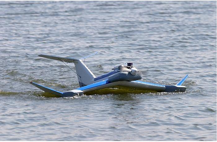
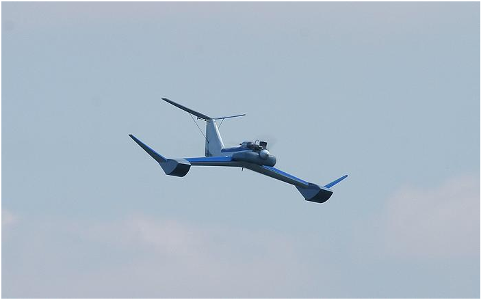
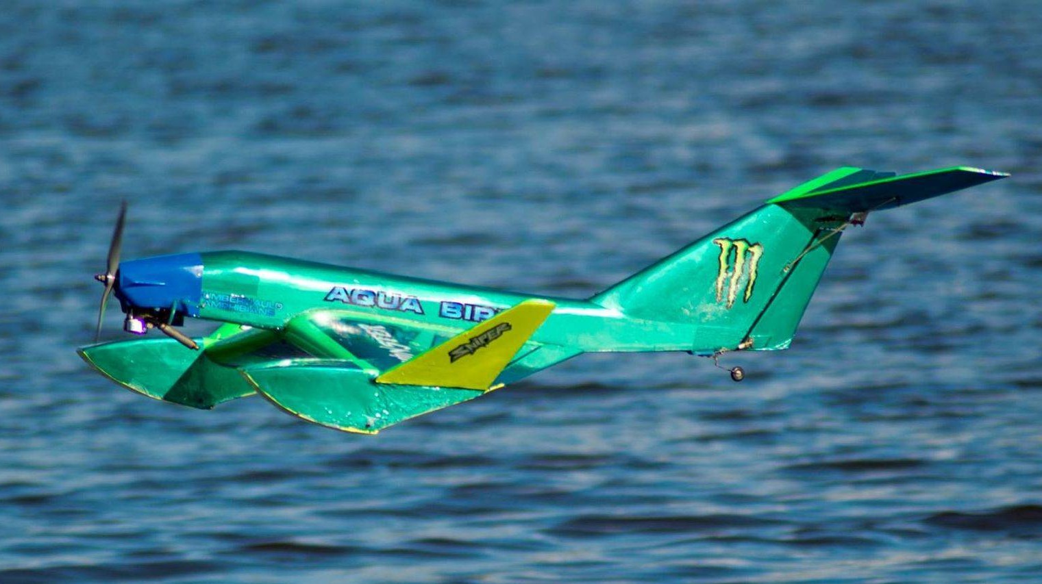
Ok, now lets see what I have for the month of July 2025. How about we try something different for this months selection. How about a waterplane? And to make this month even more different, how about something that most of you would find not only unusual but unique. Given these requirements, this month features the Aquabird, a design by Laddie Mikulasko.


Images Source: Outerzone Aquabird Webpage.
Images Source: RCGroups Webpage Aqua-Bird Thread.
This unusual but unique waterplane design by Laddie Mikulasko was originally featured in RCM Magazine in 1992. Featuring full symmetrical airfoil extended gull wings (foam core wing construction) and a built-up all-wood fuselage shown on the three large, detailed plan sheets. With a suitable .40-.46-size 2-stroke engine it's a breeze to fly and can be fitted with wheels for normal land flying field operations too!
Please note - Much of the following description was extracted or paraphrased from the article written by Laddie Mikulasko and published in a 1992 issue of RCModeler's Magazine.
RC MODEL CONSTRUCTION: The description of the building sequence will be short, describing the key steps only, as I'm pretty sure that beginners will shy away from building this model. The model is moderately complex, but should pose no difficulty for an average builder. To build the model I would suggest building the wing and winglets first. Per the RCM plans, the wing and winglets are cut out of foam with hot wire, and sheeted with 1/16″ balsa sheet. I was able to find a very good RC Groups build log for a Aquabird Electric Build that has built-up wings versus the foam core in the plans. There are many images of the build included, along with discussions on the materials selected for the wing build. Below are just three of them.
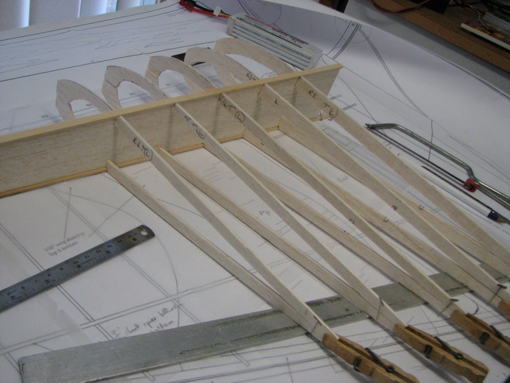
Images Source: Aquabird Electric Build
Empennage: The vertical fin and rudder are built in two halves to be joined later. To build the fin, pin the ribs down and glue leading and trailing edges to them. Glue the spar in place and sand to the contours of the ribs. Sheet this half with 1/16″ balsa. Glue in the NyRod for elevator control. Build the other half the same way. Join both halves together. The rudder is built in similar fashion. Sand fin and rudder to your satisfaction. At the top of the fin, make a V-notch to accept the stabilizer later on. The horizontal stabilizer and elevators are cut out from 1/4″ sheet balsa as shown on the plans. The stabilizer halves are joined together using the plywood dihedral brace to set the correct angle, and to reinforce the joint. Sand the leading and trailing edges to
the shape shown on the plans.
Fuselage: The fuselage is a simple 1/8″ Lite ply sides and formers construction. Depending on the type of engine used, the shape of the cowl can be changed so that it hides the muffler with the engine inverted. The inside of the fuselage must be protected by dope or preferably with epoxy or polyester resin. The model can be finished using your favorite technique.
FLIGHT CHARACTERISTICS: During take-off the model picks up speed quickly and becomes airborne in no time. The Aquabird responds to all commands immediately and precisely. The model behaved the same as a conventional low wing model in every respect and is very stable. The turns are precise with the flat bottom winglets creating enough lift to offset some loss of lift on the inboard wing when in a turn. During the stalls, the model will drop one wing and make half a turn before it recovers. Landings are beautiful, with no tendency to dig in with the sponsons and the propeller is high above the water surface during taxiing and take-off. Because of the anhedral and large sponsons, water can't get into the fuselage so the radio does not get wet.
- Aquabird RC Model Specifications:
- Aircraft Type: Sport Amphibian
- Wing Span: 60″
- Wing Chord: 120″ (Average)
- Total Wing Area: 750 sq. in. (Approx.)
- Wing Location: Low Wing
- Airfoil: Symmetrical
- Wing Platform: Modified Delta with Winglets
- Fuselage Length: 56.375″
- Fuselage Width: 3″
- Horizontal Stabilizer Span: 23.5″
- Horizontal Stabilizer Chord: 6.125″ (including elevator)
- Horizontal Stabilizer Area: 145 sq. in.″
- Stab Airfoil Section: Flat
- Vertical Stabilizer Height: 9″
- Vertical Stabilizer Chord: 11″ (including rudder)
- Rec. No. of Channels: 4 - Throttle, Rudder, Elevator, and Ailerons
- Fuel Tank Size: 10 - 12 oz.
- Landing Gear: Conventional Tail Dragger (Optional)
- Ready to Fly Weight: 112 oz. depending on power system selection
- Glow Fuel Engines: .40 – .45 cu. in. two-stroke
- Electric Powered: Output of 800 - 900 watts, 60 - 80 Amp ESC, 4-cell LiPo pack sized up to 5,000 mah.
The Aquabird RC model in this months edition can be built using the RCM Plan #1125 and RCM article available at AeroFred.com and Outerzone.co.uk Websites. Full-size Plans (for built-up wing) and RCM Article, Molded ABS Cowlings, Laser Cut Wood Pack, additional Wood Pack, and even a Short Kit Set are all available from sarikhobbies.com.
AeroFred Aquabird Webpage
Outerzone Aquabird Webpage
I hope you have enjoyed this months selection, and just maybe, I have spurred some interest in trying your hand at building an RC model airplane.
Until next month - Keep the Balsa Dust Flying!!
Build of the Month Series - June 2025 Edition
I hope you enjoyed last months BOTM WW-II Mini-Series 8th Edition on the Junkers Ju-87 RC model. If you have an RC model that you would like to see featured in this section or feel others may find interesting, please let me know and I will make every attempt to find scratch build plans, photos, and maybe even a published build article, which will then post in a future edition. Just send me an email @: Build of the Month.
Ok, now lets see what I have for the month of June 2025. Since the main purpose of my BOTM Series is to help newcomers to the hobby of RC flying, I'm going to end the WW-II Mini-Series for now and move back to something that is not only easy to build, but fun to fly and is economical. Given these requirements, this month features the RCModeler's Small Wonder, another classic design by George F. Jennings.
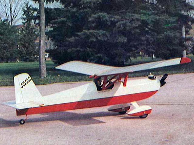
Images Source: Outerzone Small Wonder Webpage.
Please note - Much of the following description was extracted or paraphrased from an article written by George F. Jennings, and published in the January 1977 issue of RCModeler's Magazine.
The Small Wonder is a fun airplane. You can relax, have a ball, and fly as much as you like on a minimum investment with this RC model airplane. I have always liked the look of a parasol airplane. Some of my best memories of RC flying go back some 25+ years to when I built and flew my first parasol, a Great Planes Pete-n-Poke. The Pete-n-Poke was a great flyer and gave me my first taste of true success in the form of consistent flight performance.
The George F. Jennings Small Wonder is an effort to duplicate the fun and relaxed flying he had with his first parasol RC model, a Petite Parasol, except with a modern home-built flair added. Stolp Starlet, Baby Ace, and Pober Pixie are all examples of modern day parasol designs that have become popular with the Experimental Aircraft Association (EAA) members everywhere. The Small Wonder is a scale-like airplane that could very easily have a full-size counterpart hiding in some EAA'ers garage.
With 320 square inches of wing area, a three channel radio, an O.S. .15 2-stroke RC engine, and a healthy epoxy paint finish, the flying weight is approximately 40 ounces. This results in a wing loading of 18.0 oz. per sq. ft. and is right in the ballpark for a first time RC flyer. If you want a real floater, use an .09 engine, and cover with Solarfilm or similar light weight heat shrink covering, and it should weigh-in at 36 ounces, or less!
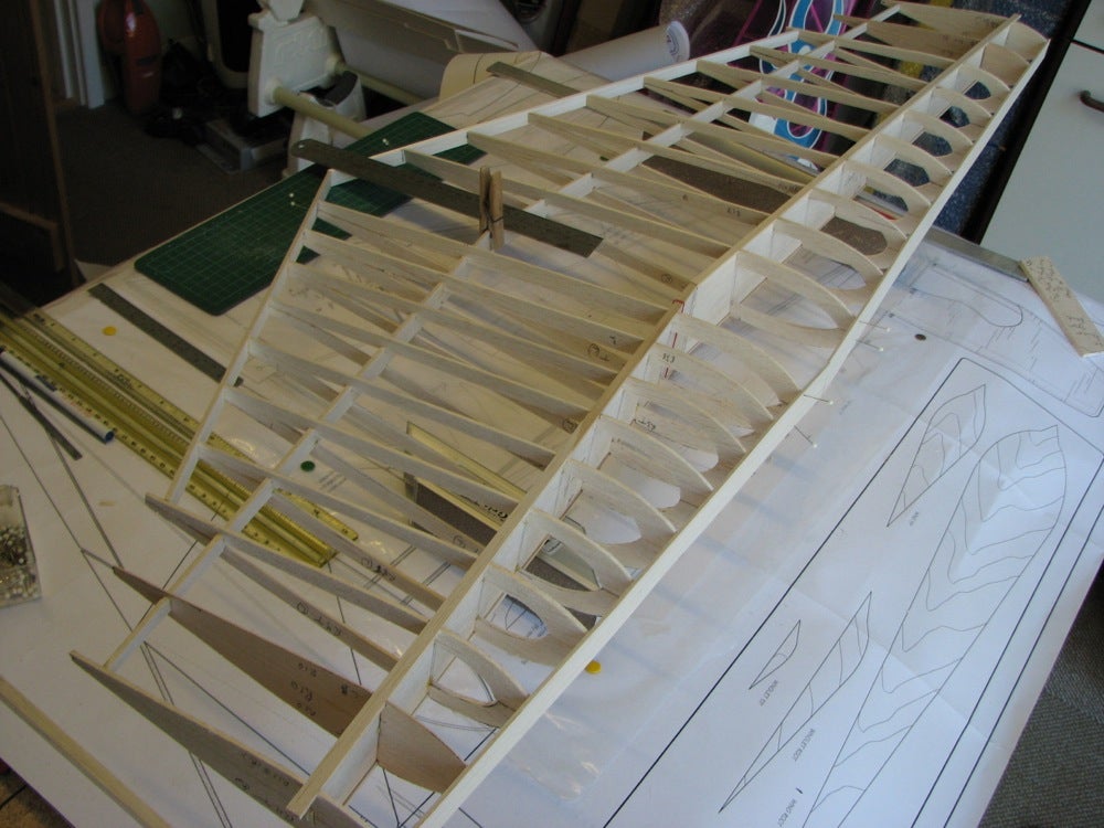
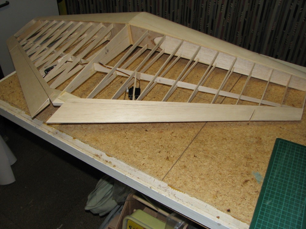
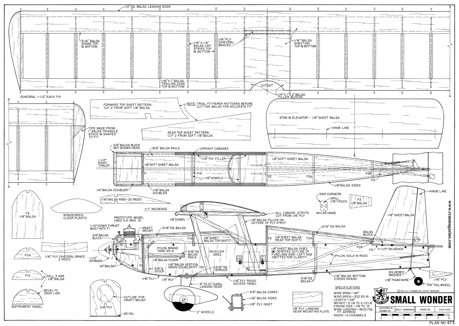
Building a Small Wonder is easy, quick, and economical. With a flat bottom wing (using twenty identical cut 1/16″ balsa sheet ribs) that you can build directly over your wax paper covered plan, 1/8″ balsa sheet fuselage and vertical/horizontal stabilizers, and minimal fuselage formers all make this RC model is an excellent choice for a first time scratch build. If desired, a conversion to electric power should not be difficult given the radio compartment hatch on the bottom of the fuselage is held in place with screws. This is a definite plus.
One recommended modification is to make the fuel tank floor removable. This is done in order to remove the tank after construction in case of a problem. A triangle shaped shelf can be added to the rear of the firewall. The tank floor then sits on top of the triangle and is held up in place by foam around the battery pack. Don't let the curved fuselage top and cabane struts throw you. George has engineered out the hard part. The 8 pages of building instructions in the RCModeler's article are very easy to follow along with being complete, and have several pictures to aid in the build. They are written so that as each step is finished, that step can be checked off. This method, if followed, should keep you from building any part out of sequence. Just follow the steps in the RCModeler's article and in a few evenings you too will have a very nice parasol model that will provide you with many hours of fun and relaxed flying.
In the flight performance department the Small Wonder excels. Take-offs are effortless and require very little rudder correction. Lift-off is smooth with no zoom and, once airborne, this RC model is rock solid and goes where you point her. With an .09 engine in the nose, flight is slow and relaxed; however, a .15 provides enough zing to really tear up the sky. You may even be able to invent some aerobatic maneuvers of your own! Landings are easy with good control all the way in, and once back on the ground you will be delighted with the ground handling. It is truly a Small Wonder!
- Small Wonder Specifications:
- Aircraft Type: Sport Trainer
- Wing Span: 46″
- Wing Chord: 7″
- Total Wing Area: 320 square inches
- Wing Location: Parasol Wing
- Airfoil: Flat Bottom
- Wing Platform: Constant Chord
- Dihedral @ each Wingtip: 1.5″
- Fuselage Length: 28″
- Stabilizer Span: 15.75″
- Stabilizer Chord: 4.375″
- Stabilizer Area: 65.5 square inches″
- Stab Airfoil Section: Flat
- Vertical Fin Height: 5″
- Vertical Fin Width (incl. rudder): 3.75″ average
- Rec. No. of Channels: 3 - Throttle, Rudder, and Elevator
- Fuel Tank Size: 4 oz.
- Landing Gear: Conventional Tail Dragger
- Ready to Fly Weight: 36 - 40 oz. depending on power system selection
- Glow Fuel Engines: .09 - .15 2-stroke
- Electric Powered: Output of 200 - 300 Watts, 30 - 40 Amp ESC, 3 cell 45C LiPo pack of 1,500 - 2,200mah.
The RCModeler's Small Wonder RC model in this months edition can be built using the RCM Plan #673 and RCM article available at AeroFred.com and Outerzone.co.uk Websites.
AeroFred Small Wonder Webpage
Outerzone Small Wonder Webpage
I hope you have enjoyed this months selection, and just maybe, I have spurred some interest in trying your hand at building an RC model airplane.
Until next month - Keep the Balsa Dust Flying!!
Build of the Month WW-II Mini-Series - May 2025 Edition
I hope you enjoyed last months BOTM WW-II Mini-Series 7th Edition on the Top Flite Vought F4U Corsair model. If you have an RC model that you would like to see featured in this section or feel others may find interesting, please let me know and I will make every attempt to find scratch build plans, photos, and maybe even a published build article, which will then post in a future edition. Just send me an email @: Build of the Month.
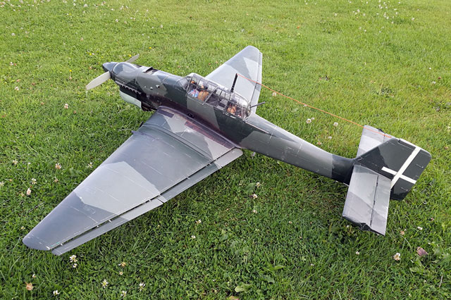
Ok, now lets see what I have for the month of May 2025. Continuing with the “BOTM WW-II Mini-Series,” for the 8th Edition we will move back to the European Theater. How about a fighter that is easily recognizable by its inverted gull wings and fixed spatted undercarriage. Given these requirements, this 8th (and final) Edition of my BOTM WW-II Mini-Series features the Junkers Ju-87, a fighter manufactured by the Germany.
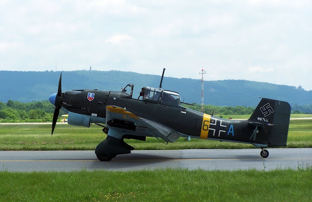
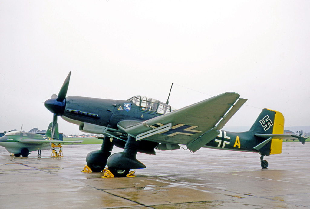
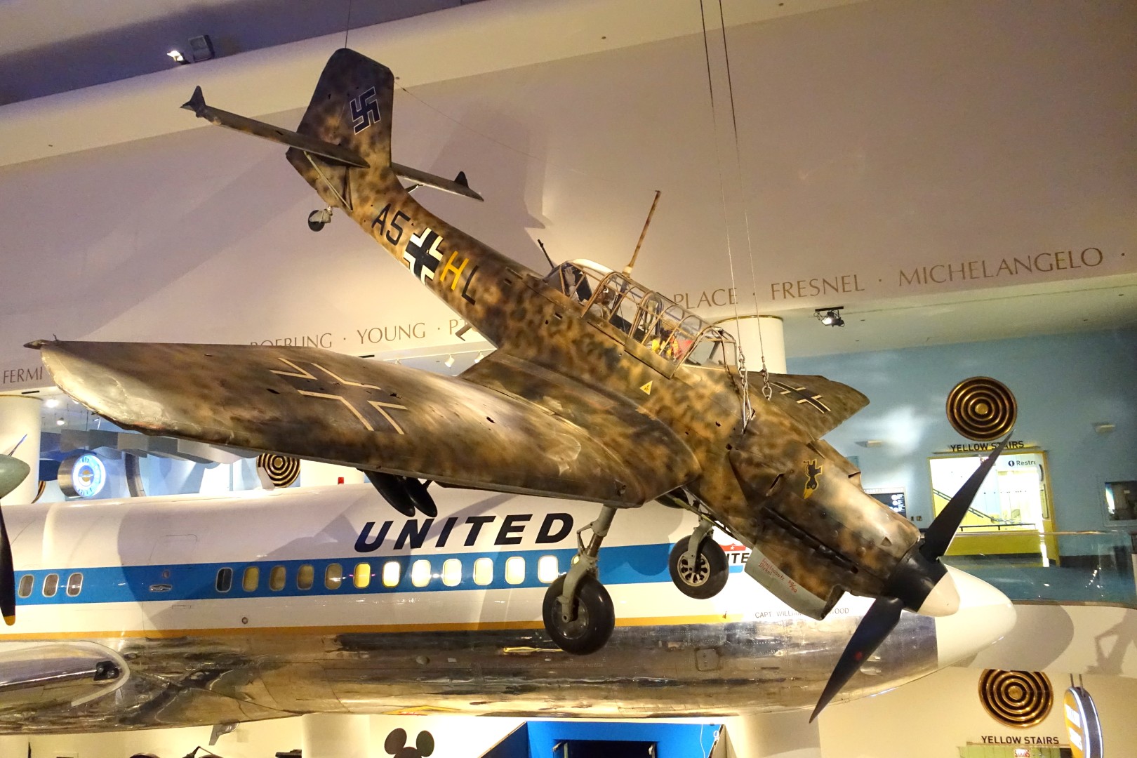
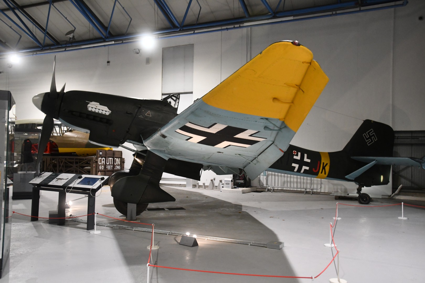
Images Source: Wikipedia Junkers Ju-87 Webpage.
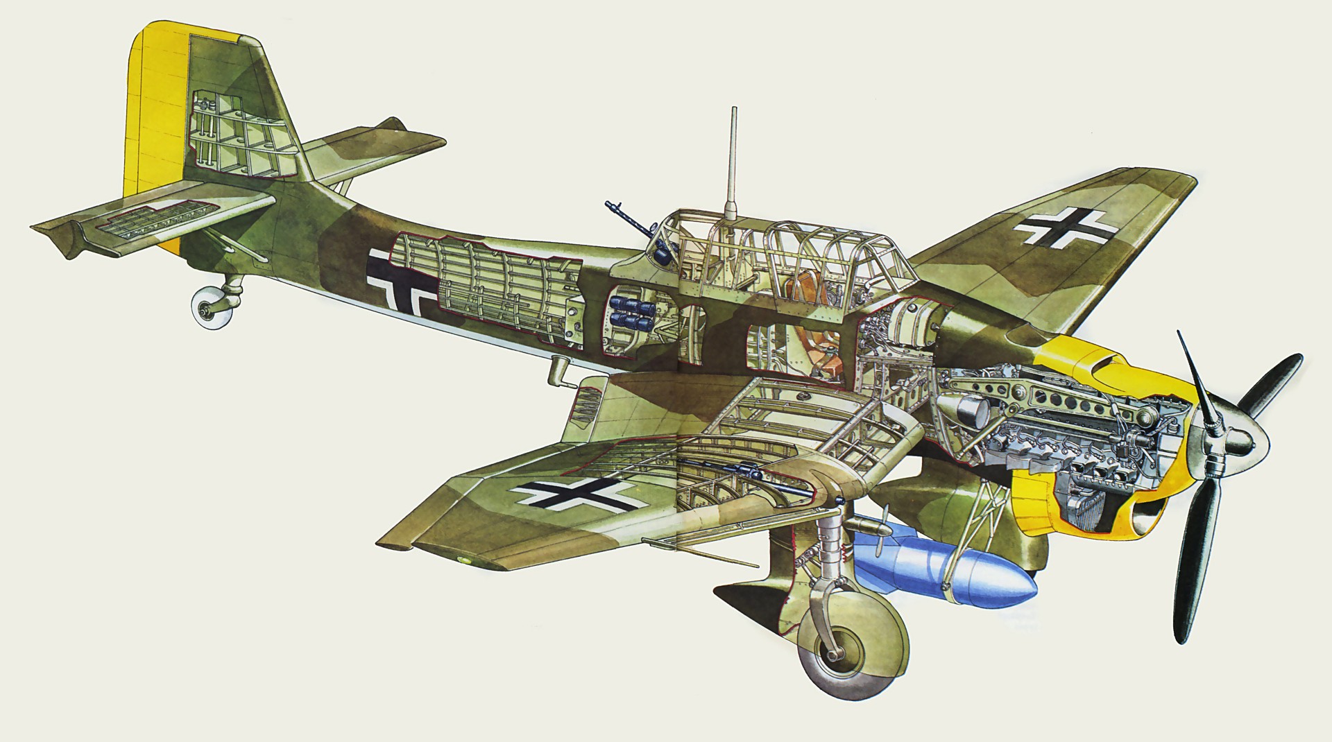
Cutaway Drawing Image Source: Cutaway Drawings Webpage.
The Junkers Ju-87, popularly known as the “Stuka”, is a German dive bomber and ground-attack aircraft. Designed by Hermann Pohlmann, it first flew in 1935. The Ju-87 made its combat debut in 1937 with the Luftwaffe's Condor Legion during the Spanish Civil War of 1936–1939 and served the Axis in World War II from beginning to end (1939–1945).
The aircraft is easily recognizable by its inverted gull wings and fixed spatted undercarriage. Upon the leading edges of its faired main gear legs were mounted ram-air sirens known as Jericho trumpets, which became a propaganda symbol of German air power and of the so-called Blitzkrieg victories of 1939–1942, as well as providing Stuka pilots with audible feedback as to speed. Stuka's design included several innovations, including automatic pull-up dive brakes under both wings to ensure that the aircraft recovered from its attack dive even if the pilot blacked out from the high g-forces, or suffered from target fixation. One of the Ju-87C's most unusual features was landing gear struts that could be blown off with explosive bolts, to allow the airplane to ditch without the fixed gear digging in and flipping it.
The Ju-87 operated with considerable success in close air support and anti-shipping roles at the outbreak of WW-II. It led air assaults during the Invasion of Poland in September 1939. Stukas proved critical to the rapid conquest of Norway, the Netherlands, Belgium, and France in 1940. Though sturdy, accurate, and very effective against ground targets, the Stuka was, like many other dive bombers of the period, vulnerable to fighter aircraft. During the Battle of Britain of 1940–1941, its lack of maneuverability, speed, or defensive armament meant that it required a heavy fighter escort to operate effectively.
After the Battle of Britain, the Luftwaffe deployed Stuka units in the Balkans Campaign, the African and the Mediterranean theaters and in the early stages of the Eastern Front war, where it was used for general ground support, as an effective specialized anti-tank aircraft and in an anti-shipping role. Once the Luftwaffe lost air superiority, the Stuka became an easy target for enemy fighters, but it continued being produced until 1944 for lack of a better replacement. By 1945 ground-attack versions of the Focke-Wulf Fw 190 had largely replaced the Ju-87, but it remained in service until the end of the war in 1945.
Germany built an estimated 6,000 Ju-87s of all versions between 1936 and August 1944.
- Actual Aircraft Specifications:
- Crew: Two
- Length: 11.5 m (37 ft 8.75 in)
- Wingspan: 13.8 m (45 ft 3.5 in)
- Height: 3.9 m (12 ft 9.25 in)
- Wing area: 31.9 m2 (343.37 sq ft)
- Empty weight: 3,900 kg (8,598 lb) (equipped)
- Max takeoff weight: 6,600 kg (14,550 lb)
- Power plant: 1 – Junkers Jumo 211J V-12 inverted liquid-cooled piston engine, 1,000 kW (1,400 hp) for take-off 1,050 kW (1,410 hp) at 4,300 m (14,100 ft)
- Propellers: 3-bladed Junkers constant-speed propeller
- Maximum speed: 410 km/h (255 mph, 222 kn) at 4,100 m (13,500 ft)
- Range: 1,535 km (954 mi, 829 nmi) at 5,100 m (16,730 ft) (maximum)
- Service ceiling: 7,300 m (24,000 ft)
- Guns: 2 – 7.92 mm (0.31 in) MG 17 machine guns forward firing, 1 – 7.92 mm (0.31 in) twin MG 81 machine gun to rear
- Bombs: 1 – 250 kg (550 lb) bomb beneath the fuselage and 4× 50 kg (110 lb) under-wing
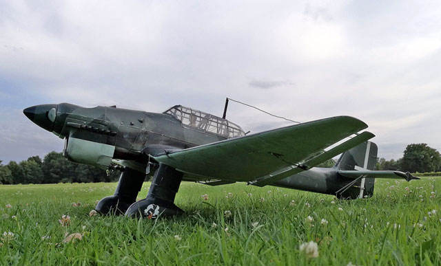

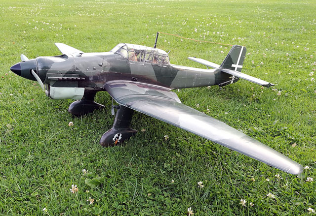

Images Source: Outerzone Junkers Ju-87B Stuka Webpage.
This months selection of the Junkers Ju-87B Stuka RC scale model is for 4-5 channels and .61 sized engines. The original plans by Royal Marutaka were updated to the re-drawn version, thanks to Ramses de Looff. The updated plan fixes the problem of the previously missing ribs and formers. His plans were then re-scaled back up to a 166cm wingspan, the same as the original Royal Marutaka kit.
With much searching of the web, I could not find much in the way of a build article for this months selection. There is an electric conversion article on the Outerzone link below, and I was able to find a April 1972 RC Modeler article on a Stuka model build, but not of the plans selected this month. But, not all is lost. I was able to locate two very nice Junkers Ju-87 Stuka “Build Threads” with lots of images and great information. The links to those I have provided to you below.
After looking over the updated plans and the build threads I can provide you with a few of my comments. As you will find for most WW-II fighter builds, this is not an RC model for someone just starting to learn how to do a scratch build. The updated plans are great, highly detailed, and provide you with all the wing ribs and fuselage former templates you will need. There also are some assembly steps and additional images showing how to build various structures. I would highly recommend anyone wanting to attempt this build to take the time and go through the build threads I have provide below. They will greatly help you in your build.
- RC Model Specifications:
- Aircraft Type: 1:8.3 Scale Warbird
- Wing Span: 65.45″
- Wing Chord: 15.5″ Root, 3.5″ Tip
- Total Wing Area: 697 square inches
- Wing Location: Low Wing
- Airfoil: Semi-Symmetrical
- Wing Platform: Double Taper
- Fuselage Length: 53.6″
- Stabilizer Span: 25″
- Number of Channels: 4-5 - Throttle, Ailerons, Rudder, Elevator, Flaps
- Ready to Fly Weight: 7-8 lbs. depending on power system selection
- Glow Fuel Engines: .61 2-stroke or .75 4-stroke
- Electric Powered: Output of 1,200-1,500 Watts, 80 Amp ESC, 6 cell 45C LiPo pack of 5,000mah.
The Junkers Ju-87B RC model in this months edition can be built using a set of plans and article available @: “Outerzone.”
Outerzone Junkers Ju-87B Stuka Webpage.
A Very Nice Junkers Ju-87 Stuka Build Thread with LOTS of Images.
Another Very Nice Junkers Ju-87 Stuka Build Thread.
I hope you have enjoyed this months selection, and just maybe, I have spurred some interest in trying your hand at building an RC model airplane.
Until next month - Keep the Balsa Dust Flying!!
Build of the Month WW-II Mini-Series - April 2025 Edition
I hope you enjoyed last months BOTM WW-II Mini-Series 6th Edition on the De Havilland DH 98 Mosquito model. If you have an RC model that you would like to see featured in this section or feel others may find interesting, please let me know and I will make every attempt to find scratch build plans, photos, and maybe even a published build article, which will then post in a future edition. Just send me an email @: Build of the Month.
Ok, now lets see what I have for the month of April 2025. Continuing with the “BOTM WW-II Mini-Series,” for the 7th Edition we will move back to the Pacific Theater again. How about a fighter with a production run that was the longest of any U.S. piston-engine fighter. Given these requirements, this 7th Edition of my BOTM WW-II Mini-Series features the Vought F4U Corsair, a fighter initially manufactured by Chance Vought.
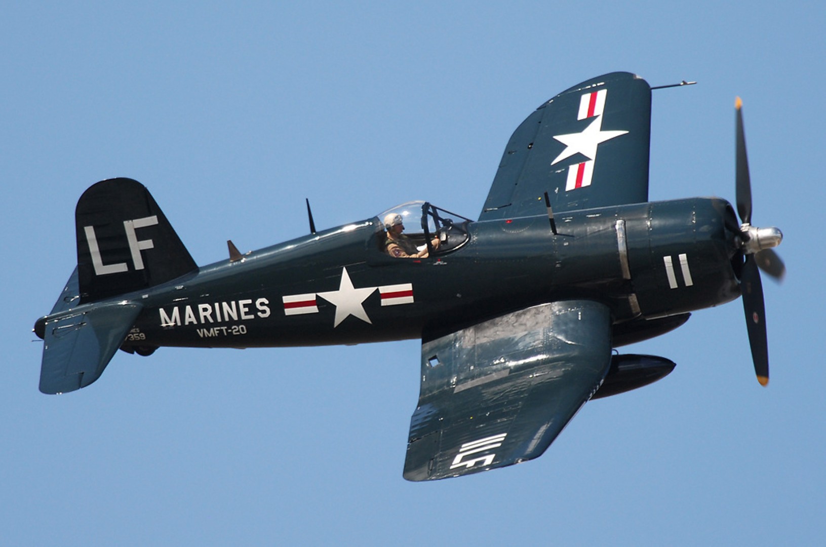
The Corsair is single-seat and single engine fighter/fighter-bomber for day and night-time, featuring a characteristic inverted gull wing (Similar to that of the Junkers Ju-87 Stuka and the Loire-Nieuport 40) and a very long propeller-blade. The development of the Corsair began following a request by the US Navy for twin and single-engine fighters in 1938, with the single-engine required to obtain the maximum speed possible and a stalling speed of no more than 110 km/h (70 mph), and a long range. Interestingly, the initial requirements comprised the aircraft to carry anti-aircraft bombs to be dropped on enemy formations. That same year, Vought – the builder company – was awarded a contract to start with the development of the Corsair, and due to their great demand, additional production contracts were given to Goodyear, whose Corsairs were designated FG, and Brewster, designated F3A.
The Corsair was designed and principally operated as a carrier-based aircraft and entered service in large numbers with the U.S. Navy and Marines in WW-II. It quickly became one of the most capable carrier-based fighter-bombers of the war. Some Japanese pilots regarded it as the most formidable American fighter and U.S. naval aviators achieved an 11:1 kill ratio. Early problems with carrier landings and logistics led to it being eclipsed as the dominant carrier-based fighter by the Grumman F6F Hellcat, powered by the same Double Wasp engine first flown on Corsair’s initial prototype in 1940. The Corsair's early deployment was to land-based squadrons of the U.S. Marine Corps and U.S. Navy.
There were problems with its carrier landing performance which was why the Navy had to opt for the Hellcat, but eventually the handling issues were resolved. The Corsair was rugged, and it boasted of speed, maneuverability and firepower which made it capable of going toe-to-toe with the legendary Zero. It was often referred to as the “Whistling Death” because of its distinctive sound. Although it's an exceptional machine, it was difficult to maintain. Nevertheless, it earned a legendary status in aviation – not only did it gain the fear and respect of its Japanese opponents, but it made quite a name for itself during WW-II, more specifically in conflicts in the Pacific Theater but it also participated in the Korean War and some French-related Cold Wars.
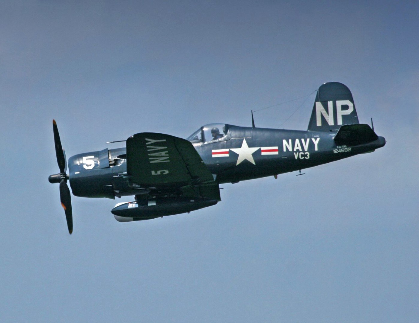
The Corsair was the most effective fighter the US Navy and the USMC had from the moment it was introduced and entered combat in the Solomon Islands in 1943. It was appraised by the pilots due to its performance and its capacity to remove the threat posed by the Mitsubishis A6M Zeros, as well as to break Japanese bombing raids. It was also capable of out-flying and out-fighting any land-based aircraft. It was capable of performing interception, bombing, ground-attack and fighter missions. The Corsair was a fighter that was also an ace-maker, with Kenneth Walsh (21 kills), Gregory “Pappy” Boyington (28 kills) and Joe Foss (26 kills). It was under Boyington lead that his squadron, the “Black Sheep” were the most effective squadron, scoring 97 kills and 103 damaged airplanes on the ground. Noteworthy to remark, the Corsair was also appraised by Admiral Nimitz giving its performance.
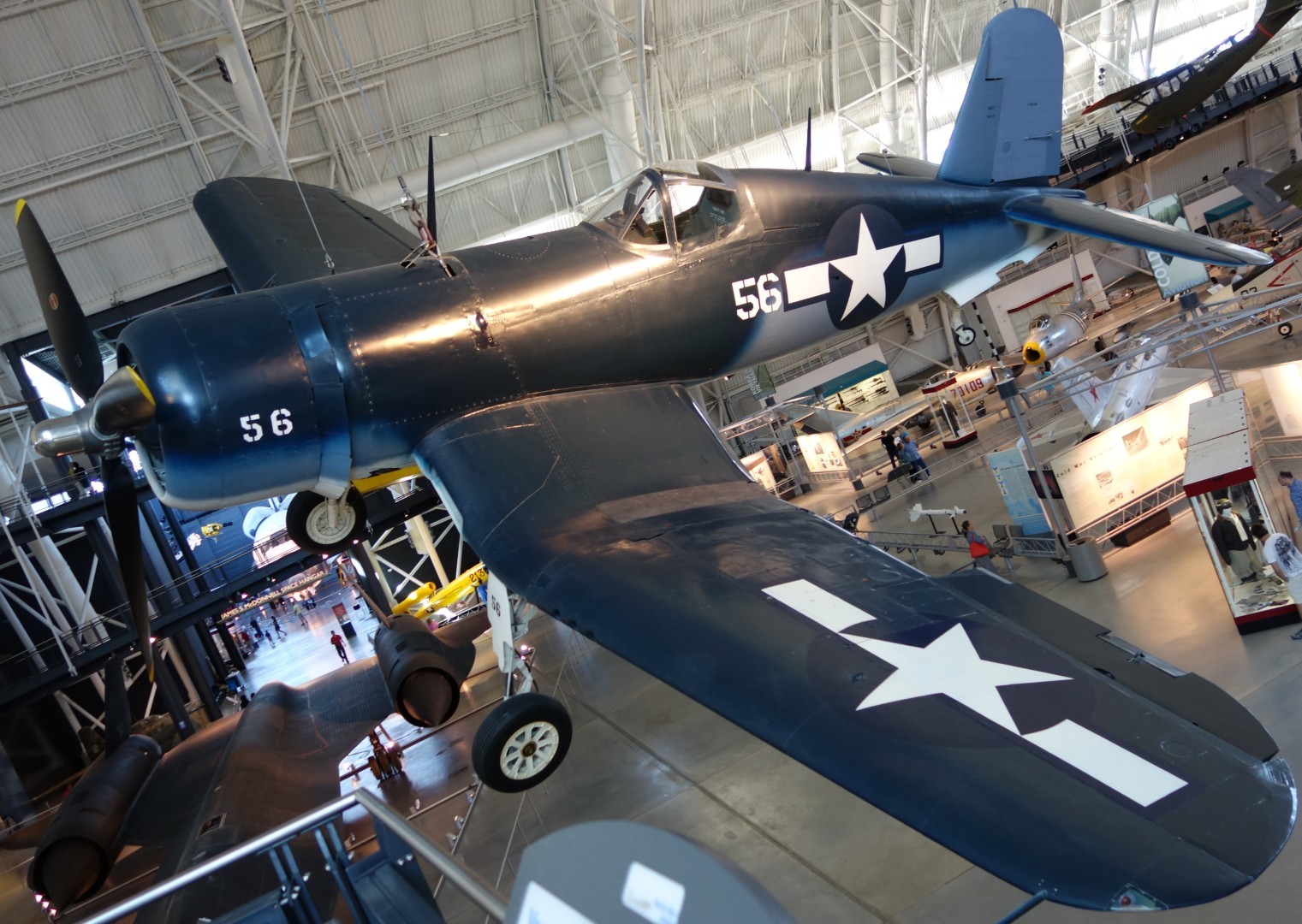
The Corsair served almost exclusively as a fighter-bomber throughout the Korean War and during the French colonial wars in Indochina and Algeria. In addition to its use by the U.S. and British, the Corsair was also used by the Royal New Zealand Air Force, French Naval Aviation, and other air forces until the 1960s. From the first prototype delivery to the U.S. Navy in 1940, to final delivery in 1953 to the French, 12,571 F4U Corsairs were manufactured in 16 separate models. Its 1942–1953 production run was the longest of any U.S. piston-engined fighter.
The Corsair saw action in post-WW-II conflicts such as the Korean War, the Indochina War, among others. Many served with other air forces as surplus or donated aircraft, where it served more than 30 years after WW-II was over, when it scored its last air victories and gave an honorable closure to an era past gone. Ten F2G “Super” Corsair series also served as civilian racers after the war.
- Actual Aircraft Specifications:
- Crew: One
- Length: 33 ft 8 in (10.26 m)
- Wingspan: 41 ft 0 in (12.50 m)
- Height: 14 ft 9 in (4.50 m)
- Wing area: 314 sq ft (29.17 m2)
- Empty weight: 9,205 lb (4,238 kg)
- Gross weight: 14,670 lb (6,654 kg)
- Max takeoff weight: 14,533 lb (6,592 kg)
- Power plant: 1 – Pratt & Whitney R-2800-18W radial engine, 2,380 hp (1,770 kW)
- Propellers: 4-bladed
- Maximum speed: 446 mph (717 km/h, 385 kn)
- Cruise speed: 215 mph (346 km/h, 187 kn)
- Stall speed: 89 mph (143 km/h, 77 kn)
- Range: 1,005 mi (1,617 km, 873 nmi)
- Combat range: 328 mi (528 km, 285 nmi)
- Service ceiling: 41,500 ft (12,600 m)
- Rate of climb: 4,360 ft/min (22.1 m/s)
- Guns: 6 – 0.50 in (12.7 mm) M2 Browning machine guns 375-400 rounds per gun
- Rockets: 8 – 5 in (12.7 cm) high velocity aircraft rockets
- Bombs: 4,000 lb (1,800 kg)
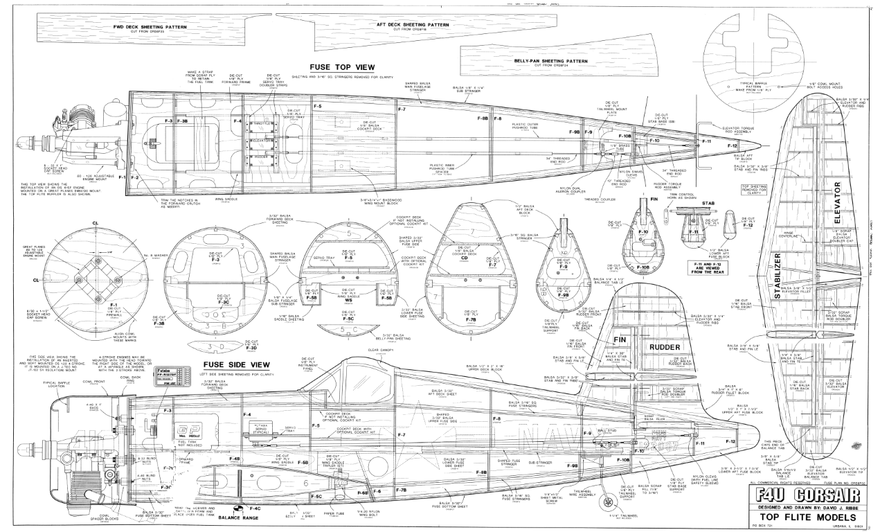
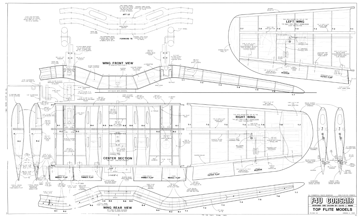
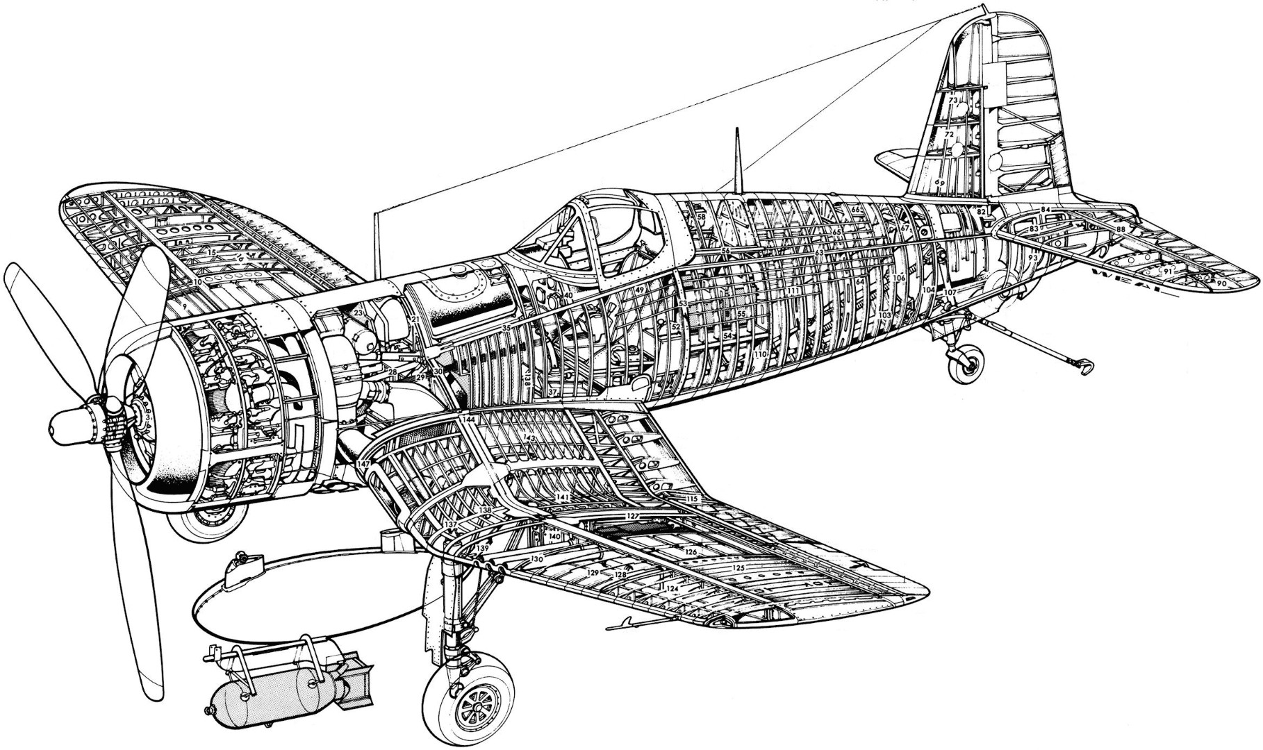
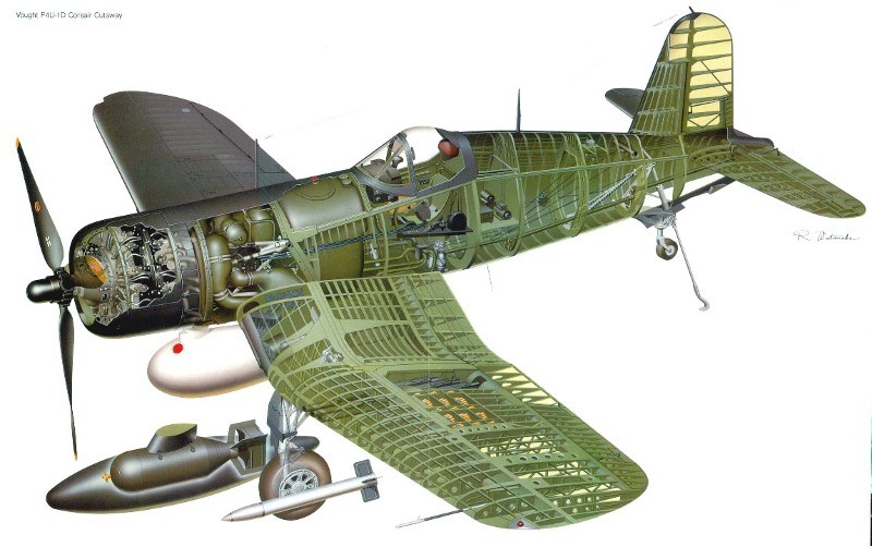
Images Source: RCGroups Forums Webpage, and Extracts from Top Flite Plans.
The Top Flite F4U Corsair is a sport scale model of the Chance Vought F4U Corsair, and the plans were designed/drawn by David J. Ribbe. This model may be built as a sport model for sport flying, or detailed out for sport scale competition. Either way, the model possesses a very good scale outline. NOTE - This RC model aircraft is not for beginners, and doing a scratch build using the Top Flite plans is not something for a scratch build beginner. I say this because the Top Flite plans do not contain profiles for all the wing ribs, but the instruction manual does have images of all the die-cut parts. These could be used, if resized to match the full size plans, to make the needed rib templates. Additionally, the wing sheeting on this model is complex and will require some experience in working with balsa sheeting.
The Top Flite Instructions show an OS .61 2-stroke engine side mounted at a 45 degree inverted position. It also shows a Top Flite internal muffler (TOPQ7915). This power package should work very well. The instructions also show the installation of an OS 1.20 4-stroke engine. Even though it is shown mounted inverted, it could also be mounted upright or on its side; the decision is yours. Flexible exhaust systems are available for most 4-stroke engines and there is more than enough room inside the Corsair's cowl to route the exhaust out the bottom. You would also have to change the cowl mounting.
You must decide early in the building process if you are going to use operating wing flaps. These are not required but do add to the Corsair's appearance and flyability. The flaps as described in the instruction manual work very well, giving super stable slow flight with virtually no trim changes. Obviously there is some extra work and craftsmanship required to fit operating flaps to the model. If you use operating flaps, you will need to have (2) standard servos and small Robart hinge points (ROBQ2508) available during the build.
You will need to decide early in your build whether you intend to use retractable landing gear in your Corsair. The Top Flite Corsair is designed to work with the Robart ninety degree rotating retracts (ROBQ1815). Century Jet Models ninety degree rotating retracts (CJMQ3055) are specifically made for this model and will work equally as well. The Century Jet retracts include functional struts as part of a complete kit. Finding retracts may be an issue. There are many reviews and forums on the web that discuss this further.
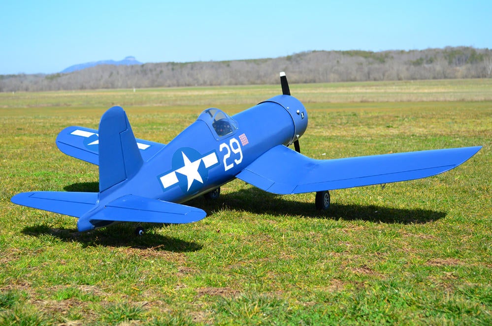
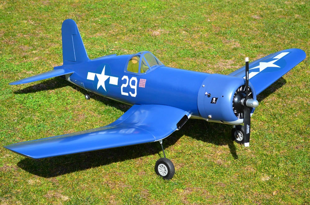
The Top Flite F4U Corsair is a great flying sport scale airplane that flies smoothly and predictably, yet is highly maneuverable. It does not have the self-recovery characteristics of a primary trainer. Therefore, you must either have mastered the basics of R/C flying or seek the assistance of a competent R/C pilot to help you with your first flights.
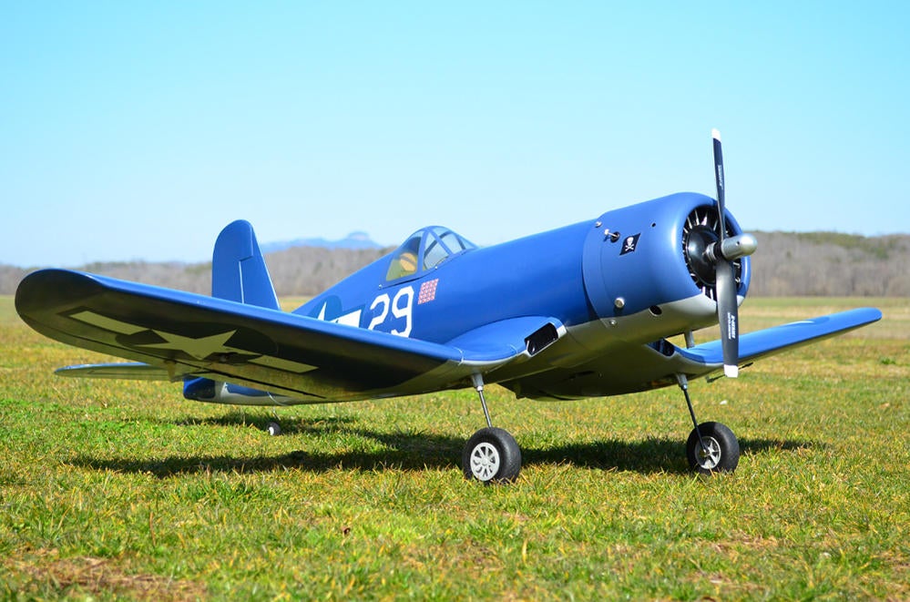
- Top Flite F4U Corsair RC Model Specifications:
- Aircraft Type: 1/8th Scale Warbird
- Wing Span: 62.5″
- Total Wing Area: 700 square inches
- Wing Location: Low Wing
- Airfoil: Semi-Symmetrical
- Wing Platform: Double Taper
- Fuselage Length: 50.5″
- Number of Channels: 6 - Throttle, Ailerons, Rudder, Elevator, Flaps, and Retract Gear
- Ready to Fly Weight: 8.5 - 9.5 lbs. depending on power system selection
- Glow Fuel Engines: .60 - .80 2-stroke .90 - 1.20 4-stroke
- Electric Powered: Output of 1,200 - 1,800 Watts, 80-100 Amp ESC, 6 cell 45C LiPo pack of 5,000mah
The Vought F4U Corsair RC model in this months edition can be built using a set of Top Flite Plans and Instructions available @: “Outerzone”
A Top Flite F4U RCM&E Build Blog with Pictures.
Outerzone Vought F4U Corsair Webpage.
I hope you have enjoyed this months selection, and just maybe, I have spurred some interest in trying your hand at building an RC model airplane.
Until next month - Keep the Balsa Dust Flying!!
Build of the Month WW-II Mini-Series - March 2025 Edition
I hope you enjoyed last months BOTM WW-II Mini-Series 5th Edition on the Supermarine Spitfire model. If you have an RC model that you would like to see featured in this section or feel others may find interesting, please let me know and I will make every attempt to find scratch build plans, photos, and maybe even a published build article, which will then post in a future edition. Just send me an email @: Build of the Month.
Ok, now lets see what I have for the month of March 2025. Continuing with the “BOTM WW-II Mini-Series,” for the 6th Edition we will look at a fighter that served in Europe, the Mediterranean, and the Pacific. Lets find a fighter that is a twin-engined, multi role combat aircraft, and unusual in that its airframe is constructed mostly of wood. Given these requirements, this 6th Edition of my BOTM WW-II Mini-Series features the De Havilland DH 98 Mosquito, a fighter manufactured by Great Britain.
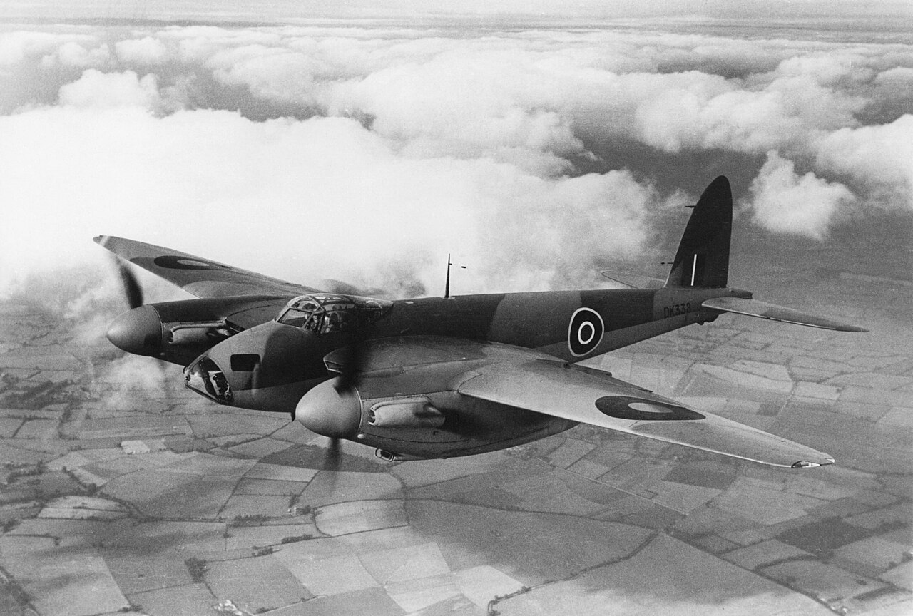
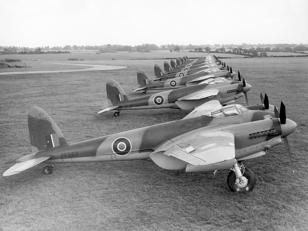
The De Havilland DH 98 Mosquito is a British twin-engined, multi role combat aircraft, introduced during the Second World War. De Havilland's design of the Mosquito came about when Britain needed a cheap, easy to build, and capable bomber. Unusual in that its airframe was constructed mostly of wood, which sped up the manufacturing process, it was nicknamed the “Wooden Wonder”, or “Mossie”. In 1941, it was one of the fastest operational aircraft in the world. Many allied and enemy airplane manufacturers sneered at the idea when the Mosquito was conceptualized, with many calling it a large model airplane.
Officials in the British Air Ministry vehemently resisted building it, but from the day production finally began in 1941 until the war ended, the Royal Air Force (RAF) never had enough Mosquitoes to perform the amazing variety of missions that air tacticians devised for this outstanding airplane. It excelled at day and night bombing from high or very low altitudes, long-range reconnaissance, air-to-air combat in daylight and darkness, and finding and striking distant targets at sea. No less than forty-two distinct versions of the DH 98 entered service. At extreme speeds, Mosquitoes carried heavy loads great distances because of two key design features: a lightweight, streamlined, wooden airframe propelled by powerful, reliable engines. The “Wooden Wonder” was constructed from Alaskan spruce, English ash, Canadian birch and fir, and Ecuadorian balsa glued and screwed together in new, innovative ways, and motivated by the world's finest reciprocating, liquid-cooled power plants, a pair of Rolls Royce Merlins. There has never been a more successful, combat-proven warplane made of wood.
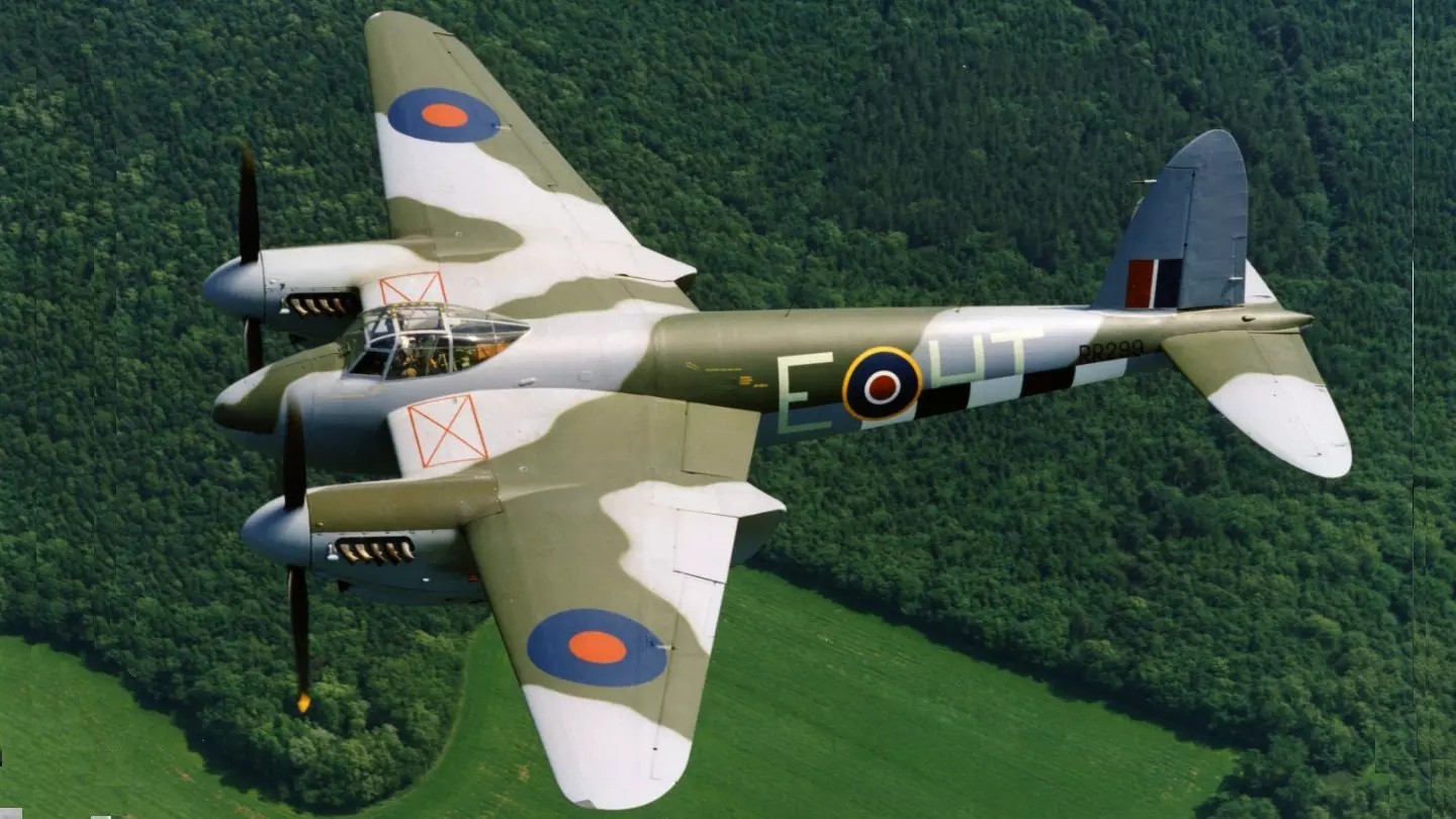
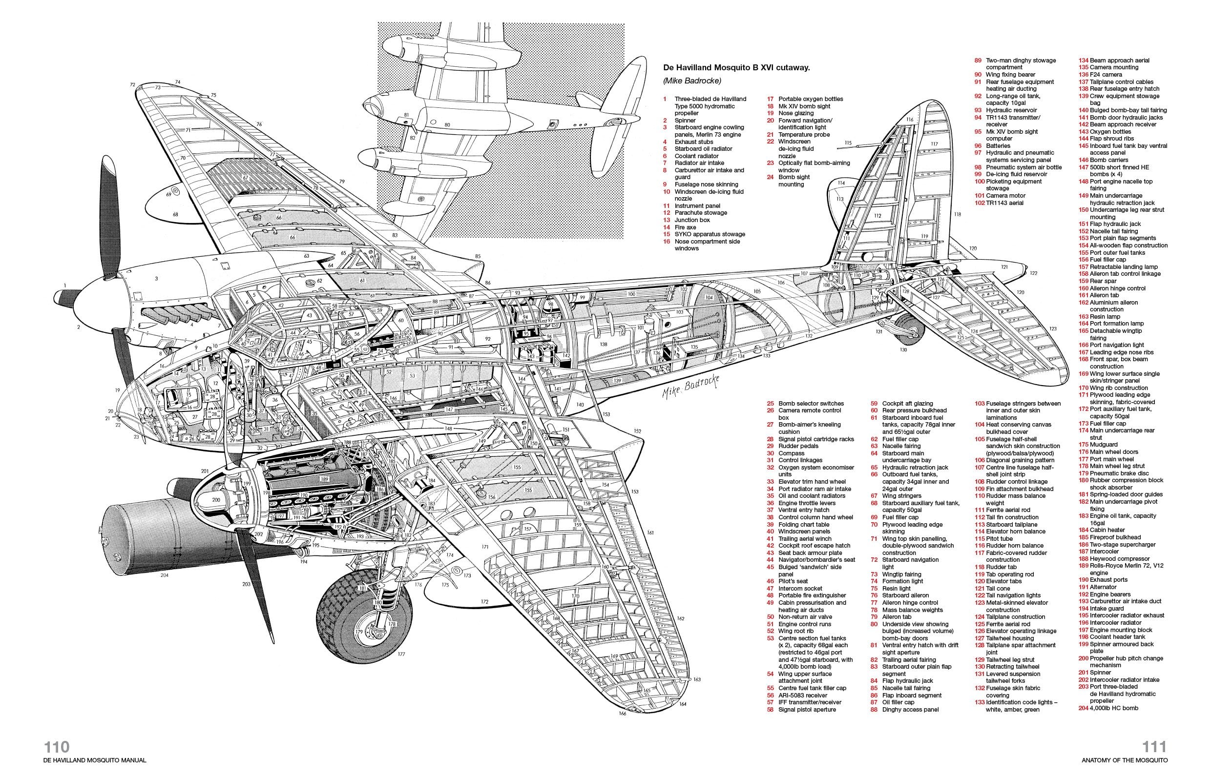
Like the Comet and Albatross wings, De Havilland built Mosquito wings out of shaped pieces of wood and plywood cemented together with Casein glue. Approximately 30,000 small, brass wood screws also reinforced the glue joints inside a Mosquito wing (another 20,000 or so screws reinforced glue joints in the fuselage and empennage). The internal wing structure consisted of plywood box spars fore and aft. Plywood ribs and stringers braced the gaps between the spars with space left over for fuel tanks and engine and flight controls. Plywood ribs and skins also formed the wing leading edges and flaps but De Havilland framed-up the ailerons from aluminum alloy and covered them with fabric. Sheet metal skins enclosed the engines and metal doors closed over the main wheel wells when the pilot retracted the landing gear.
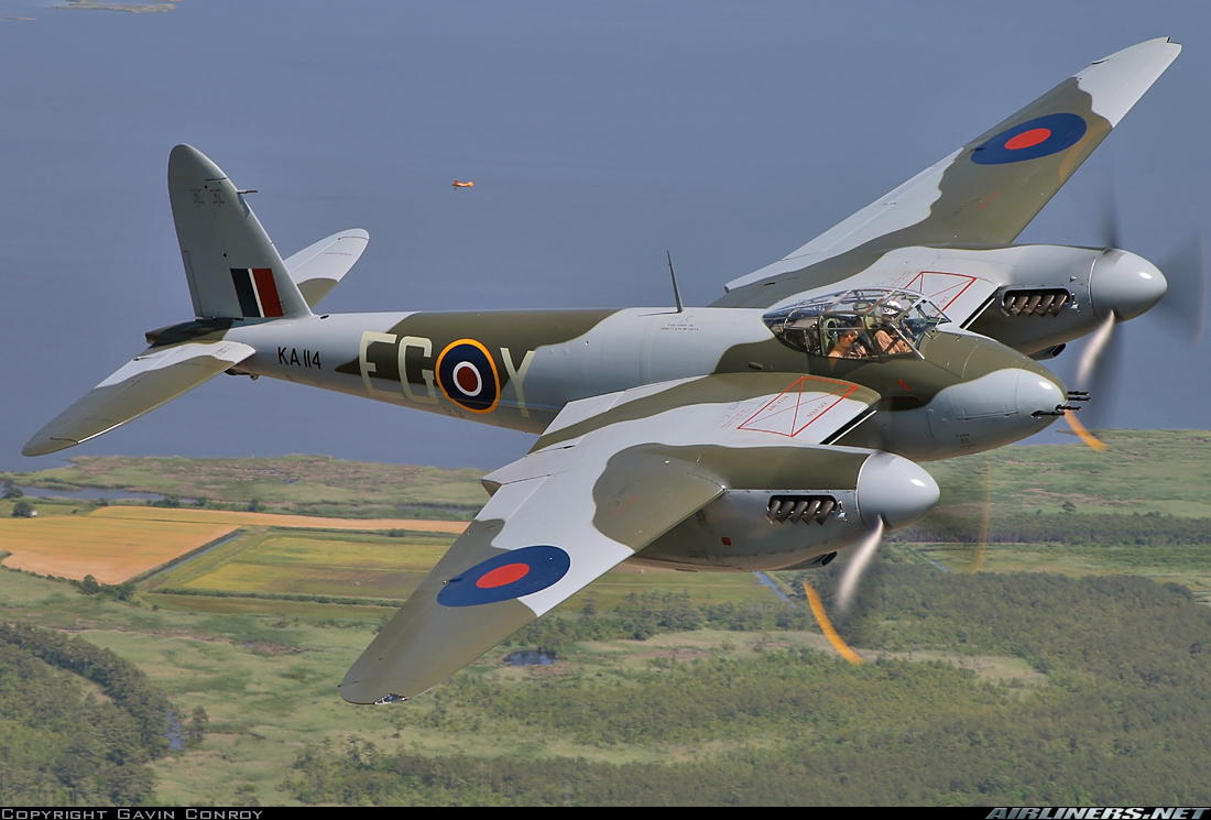
The Mosquito flew with the RAF and other air forces in the European, Mediterranean, and Italian theaters. The Mosquito was also operated by the RAF in the Southeast Asian theater and by the Royal Australian Air Force based in the Halmaheras and Borneo during the Pacific War. During the 1950s, the RAF replaced the Mosquito with the jet-powered English Electric Canberra. The Mosquito was a highly successful plane, serving the RAF in various roles. The plane’s high speed of 668 km/h and agility made it a difficult target for the enemy to shoot down. Not bad for a life-sized toy airplane!
The Mosquito flew its last war mission on May 21, 1945, searching for German submarines in waters off the coast of Scotland. In total, between 1940 and 1950, the total number of DH 98 Mosquito aircraft built was 7,781, and were manufactured in the United Kingdom, Canada, and Australia. The type serving with the main Allied air forces, including both the United States and Russia and postwar many were operated by the air forces of France, Belgium, Turkey, Sweden, Dominica, South Africa, Yugoslavia, Australia, Canada, China, Czechoslovakia, Israel, New Zealand and Norway.
- Actual Aircraft Specifications:
- Crew: Two: pilot, bomb aimer/navigator
- Length: 44 ft 6 in (13.56 m)
- Wingspan: 54 ft 2 in (16.51 m)
- Height: 17 ft 5 in (5.31 m)
- Wing area: 454 sq ft (42.2 m2)
- Empty weight: 14,300 lb (6,486 kg)
- Max takeoff weight: 25,000 lb (11,340 kg)
- Power plant: 2 – Rolls-Royce Merlin V-12 liquid-cooled piston engine, 1,710 hp (1,280 kW) each -76 driving the left propeller, -77 driving right
- Propellers: 3-bladed constant-speed propellers
- Maximum speed: 415 mph (668 km/h, 361 kn) at 28,000 ft (8,500 m)
- Range: 1,300 mi (2,100 km, 1,100 nmi)
- Service ceiling: 37,000 ft (11,000 m)
- Rate of climb: 2,850 ft/min (14.5 m/s)
- Guns: 4 – 7.7 mm Browning machine guns, 4 – 20 mm Hispano cannons
- Bombs: 4,000 lb (1,800 kg)
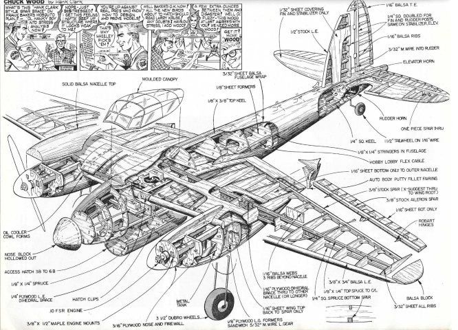
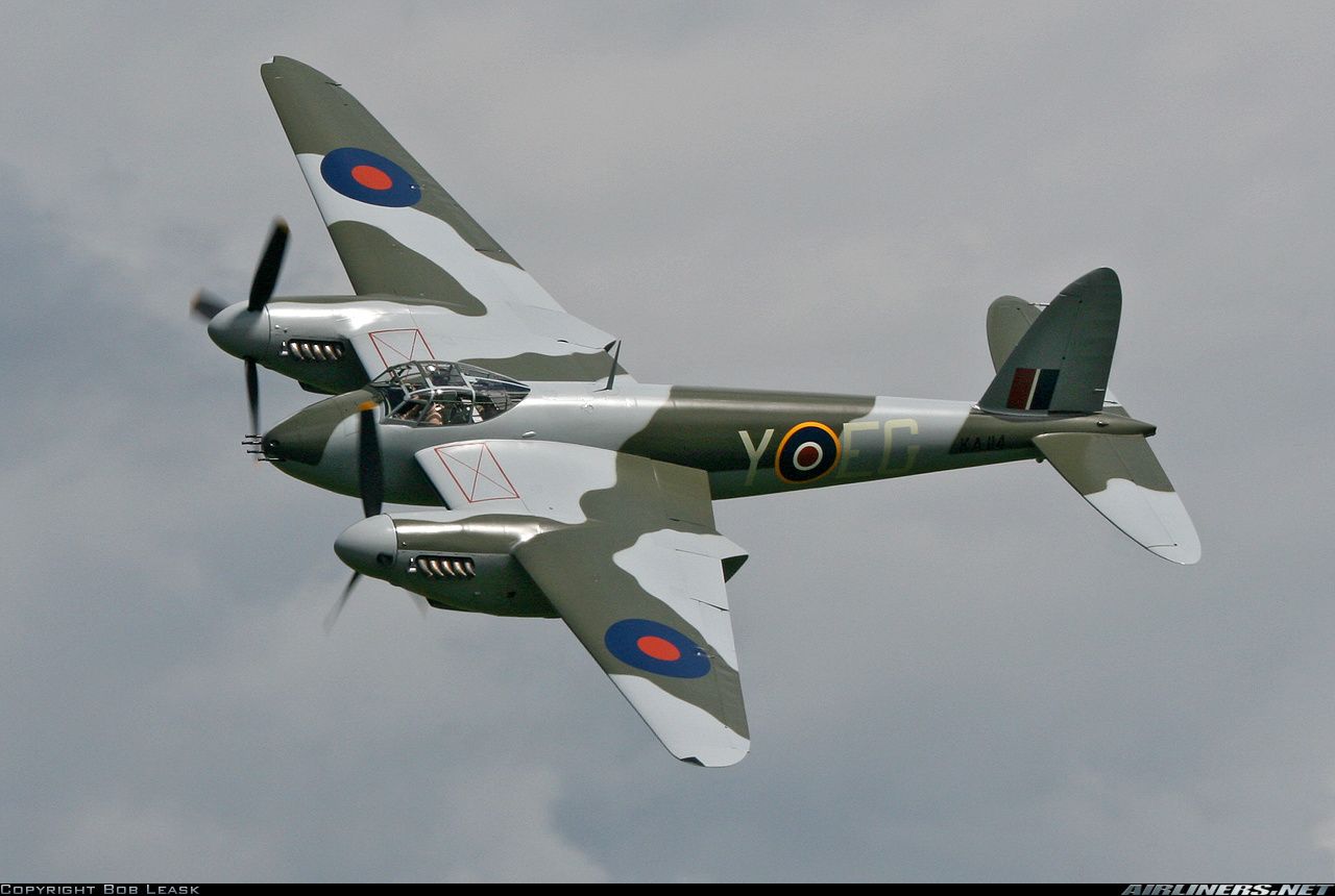
Images above were found online @: Outerzone Mosquito Webpage, extracted from article in July 1983 Model Aviation Magazine, and a Bing Search.
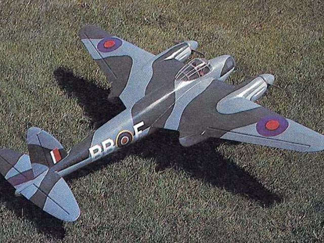
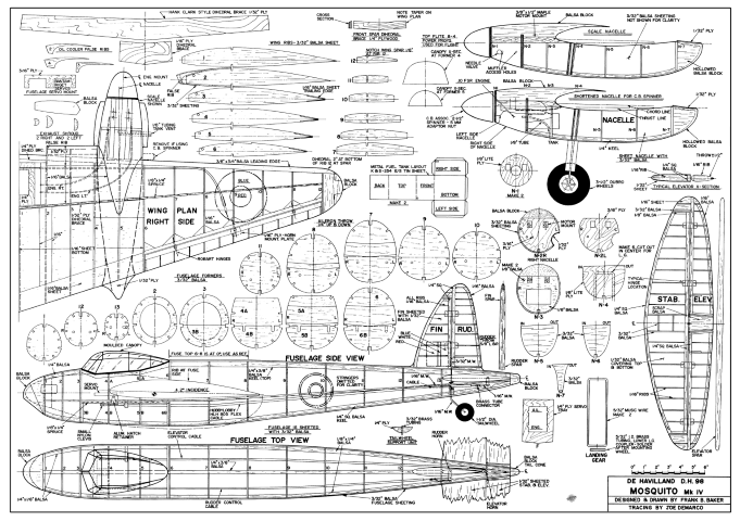
Please note - Much of the following description was extracted from an article written by Frank B. Baker and published in the July 1983 issue of Model Aviation Magazine. The De Havilland DH 98 Mosquito MK IV plans were also designed and drawn by Frank.
The Mosquito is one of the few full-sized aircraft that, when photographed, looks like a model airplane. This is due, in part, to its plywood and balsa construction that results in an exceptionally smooth exterior surface. Modelers seem to have a special affinity for this aircraft. Maybe it is because so much balsa was used in its construction. Frank started from a set of excellent drawings that appeared in the December 1966 issue of Aeromodeller. His DH 98 RC model is 1/12th scale and was designed for OS Max .10FSR engines, uses four-channel controls, and it flies perfectly at a weight of 4-1/2 pounds. It's to scale except for the out-thrusted nacelle's, a feature which gives the model amazing one-engine-out performance.
RC MODEL CONSTRUCTION: While not difficult, the Mosquito must be built in the proper order. Since this model is not for a beginner, Frank does not give a step-by-step account in his article, but he does highlight some of the major things that must be done in proper sequence, as well as, some of the innovations. His article build description starts with the wing, followed by the fuselage, engine nacelles, tail surfaces, and then finishing. This is a fairly straight forward scratch built balsa and ply RC model. Lots of ribs of varying sizes, 13 formers in the fuselage, and 7 more formers in each engine nacelle. But, that is what we “scratch builders” like, right!!
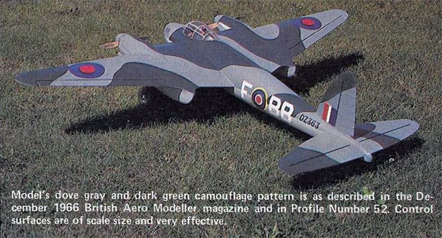
FLIGHT CHARACTERISTICS: Frank reminds his readers that this is a Scale model, and it must be flown with respect. On takeoffs the tail will lift rather quickly, but do not break ground until a lot of speed has been built up. Then use just enough elevator to lift off and climb at a modest angle of attack. Once airborne, the Mosquito is quite fast. The narrow, pointed tips make it quite sensitive to ailerons. This is especially noticeable at higher speeds. Experiment with throws until the ailerons are effective without being sudden. Landings are really fun. Set up a long, flat approach, and control the descent with the throttle. I let it keep flying in a level attitude until the wheels touch, and then I go to full engine idle. The single-engine performance is outstanding. On several flights Frank states he has lost one engine and did not realized it until on final, where he could see the stopped propeller.
A FINAL CAUTION: The gray color and the camouflage is quite effective, and it is easy to lose orientation if the plane gets too far out. Frank punched-in his Mosquito once due to visual mis-orientation and hardly scratched the plane. Keep your Mosquito RC model close. It is a lot prettier up close, and you can see what you are doing. Overall, the Mosquito is a very smooth flying model, and it looks very scale like in the air. One recommendation is to install retracts. What a sight that would be in the air!
- De Havilland DH 98 Mosquito RC Model Specifications:
- Aircraft Type: 1/12th Scale Warbird
- Wing Span: 54″
- Wing Chord: 14″ Root, 4″ Tip
- Total Wing Area: 486 square inches
- Wing Location: Mid-Wing
- Wing Platform: Double Taper
- Fuselage Length: 42″
- Stabilizer Span: 22″
- Stabilizer Chord (including elevator): 6″
- Number of Channels: 4 - Throttle, Ailerons, Rudder, Elevator
- Ready to Fly Weight: 4.5 lbs. depending on power system selection
- Glow Fuel Engines: Two .10 2-stroke
- Electric Powered: Output of 200-300 Watts each, 30-40 Amp ESC's, 3 cell 45C LiPo pack of 3,000-4,000mah.
The De Havilland DH 98 Mosquito MK IV RC model in this months edition can be built using a set of plans and article available @: “Outerzone.”
July 1983 Issue of Model Aviation Magazine.
December 1966 Issue of Aeromodeller.
I hope you have enjoyed this months selection, and just maybe, I have spurred some interest in trying your hand at building an RC model airplane.
Until next month - Keep the Balsa Dust Flying!!
Build of the Month WW-II Mini-Series - February 2025 Edition
I hope you enjoyed last months BOTM WW-II Mini-Series 4th Edition on the Ilyushin IL-2 Stormovik model. If you have an RC model that you would like to see featured in this section or feel others may find interesting, please let me know and I will make every attempt to find scratch build plans, photos, and maybe even a published build article, which will then post in a future edition. Just send me an email @: Build of the Month.
Ok, now lets see what I have for the month of February 2025. Continuing with the “BOTM WW-II Mini-Series,” for the 5th Edition we will look again at the European Theater but this time on the Western Front. How about a fighter that was the best-known British airplane of WW-II. Given these requirements, this 5th Edition of my BOTM WW-II Mini-Series features the Supermarine Spitfire, a fighter manufactured by Great Britain.
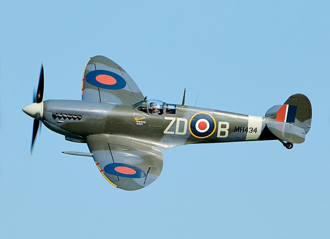
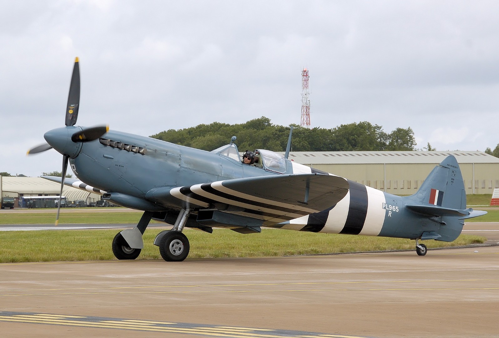
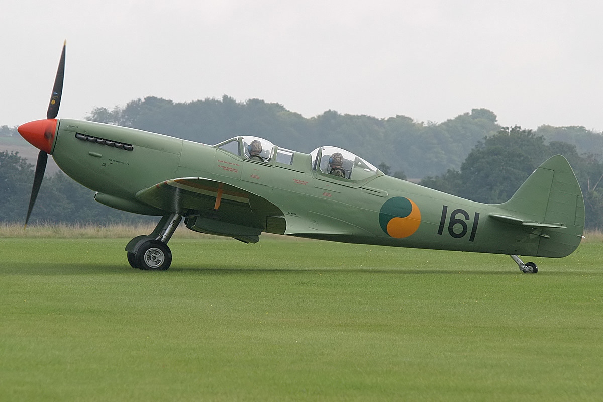
Images Source: Wikipedia Spitfire Webpage.
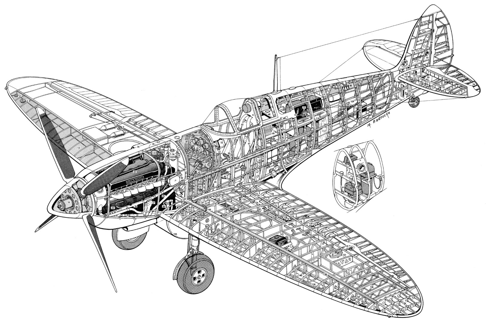
Image Source: An Illustrated Anatomy Of the World’s Fighters.
The Supermarine Spitfire is a British single-seat fighter aircraft used by the Royal Air Force (RAF) and other Allied countries before, during, and after World War II. It was the only British fighter produced continuously throughout the war. The Spitfire remains popular among enthusiasts.
The Spitfire was designed as a short-range, high-performance interceptor aircraft by R. J. Mitchell, chief designer at Supermarine Aviation Works, which operated as a subsidiary of Vickers-Armstrong from 1928. Mitchell developed the Spitfire's distinctive elliptical wing (designed by Beverley Shenstone) with innovative sunken rivets to have the thinnest possible cross-section, achieving a potential top speed greater than that of several contemporary fighter aircraft, including the Hawker Hurricane. Mitchell continued to refine the design until his death in 1937, whereupon his colleague Joseph Smith took over as chief designer.
The Spitfire is notable for its sleek, slender body, which allowed a maximum speed of 580 km/h. It’s also famous because its design and aerodynamic capabilities allowed it to sustain damage and remain in the air. This allowed pilots to withstand a beating during combat and keep on fighting, much to the enemy’s frustration.
Developed in 1938, the Spitfire was kept under wraps during the start of WW-II, with the Hawker Hurricane doing most of Britain’s aerial bidding. Soon, it became clear that the Hurricane was no match for German air superiority, forcing them to try the Spitfire. It did not disappoint!
In addition to its design, the power of the Spitfire was unmatched during WW-II. It had 8 machine guns mounted to deliver a rain of fire to bombers and ground targets alike. It was among the only airplanes that could seriously challenge the aerial superiority of the German juggernaut, the Messerschmitt Bf-109.
During the Battle of Britain, the more numerous Hurricane flew more sorties resisting the Luftwaffe, but the Spitfire captured the public's imagination as the main RAF fighter, in part because the Spitfire was generally a better fighter aircraft than the Hurricane. Spitfire units had a lower attrition rate and a higher victory-to-loss ratio than Hurricanes, most likely due to Spitfire’s higher performance. During the battle, Spitfires generally engaged Luftwaffe fighters, mainly Messerschmitt Bf 109E–series aircraft, which were a close match for them.
The Spitfire reigned the skies during the Battle of Britain as it shot down 529 enemy aircraft, effectively regaining allied control of the air and keeping Britain in the war. It went on to succeed further afield from Europe to the Mediterranean and Pacific theaters of war. In all, over 20,000 Spitfires were built in different variants.
Owing to its wide usage in WW-II and iconic status, many Spitfires have survived into preservation. Some 240 Spitfires are preserved as of 2023; this includes around 60 which are airworthy. Many air museums have Spitfires on static display, for example, Chicago's Museum of Science and Industry has paired a static Spitfire with a static Ju 87 R-2/Trop Stuka dive bomber.
- Supermarine MK 24 Spitfire Aircraft Specifications:
- Crew: One
- Length: 29 ft 11 in (9.12 m)
- Wingspan: 36 ft 10 in (11.23 m)
- Height: 11 ft 5 in (3.48 m)
- Wing area: 242.1 sq ft (22.49 m2)
- Empty weight: 5,065 lb (2,297 kg)
- Max takeoff weight: 6,700 lb (3,039 kg)
- Power plant: 1 – Rolls-Royce Merlin 45 V-12 liquid-cooled piston engine, 1,470 hp (1,100 kW)
- Propellers: 3-bladed Rotol constant-speed propeller
- Maximum speed: 370 mph (600 km/h, 320 kn)
- Range: 479 mi (771 km, 416 nmi)
- Combat range: 248 mi (399 km, 216 nmi)
- Ferry range: 1,100 mi (1,800 km, 960 nmi) with fuel tank
- Service ceiling: 36,500 ft (11,100 m)
- Rate of Climb: 2,600 ft/min (13 m/s)
- Guns: 2 – 20 mm Hispano Mk II cannon (120 rounds per gun)
- 2 – .50 in M2 Browning machine guns (250 rounds per gun)
- Rockets: 2 RP-3 rockets (1 under each wing)
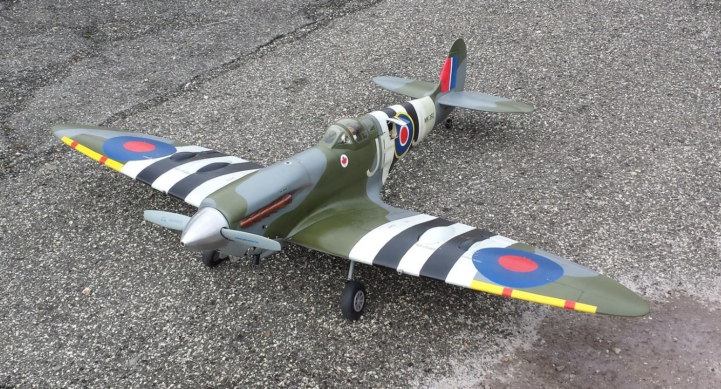
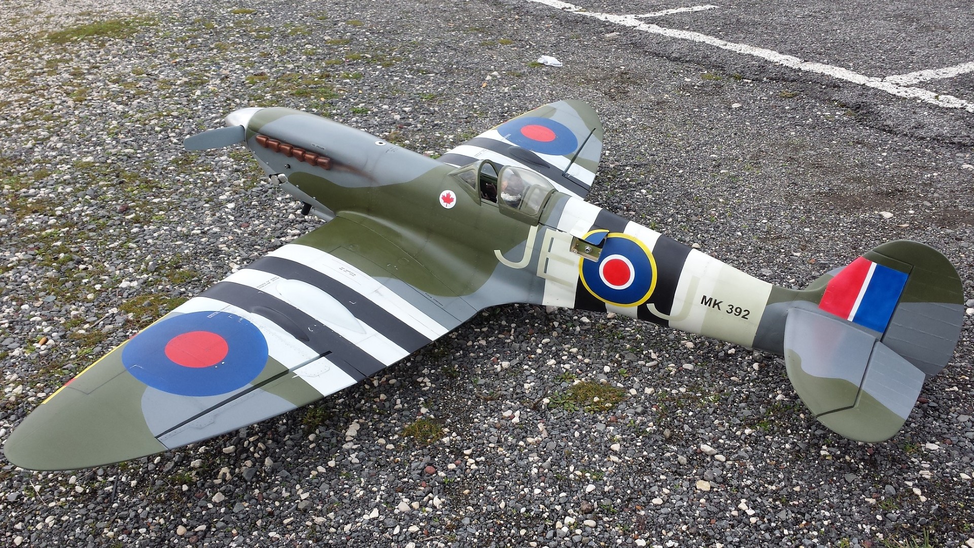
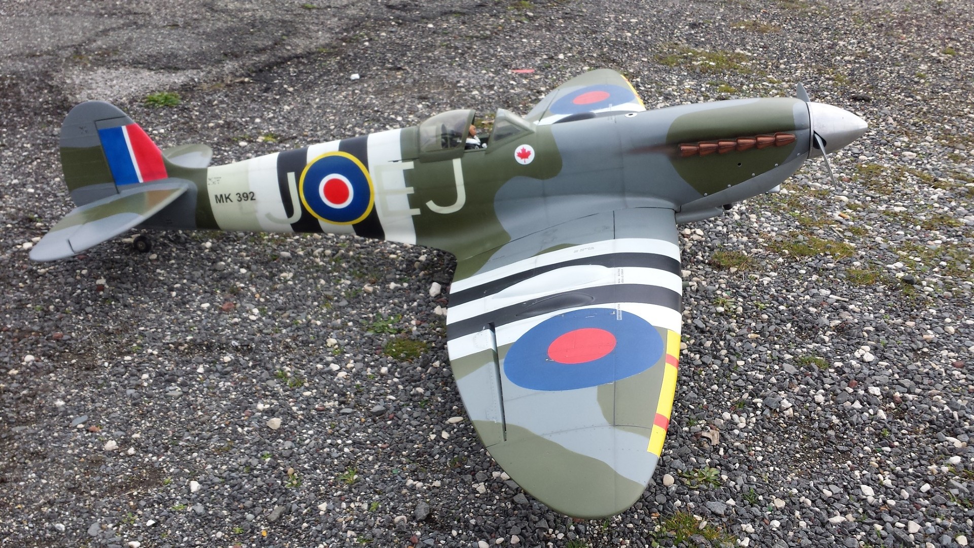
Images Source: RC Universe Webpage.
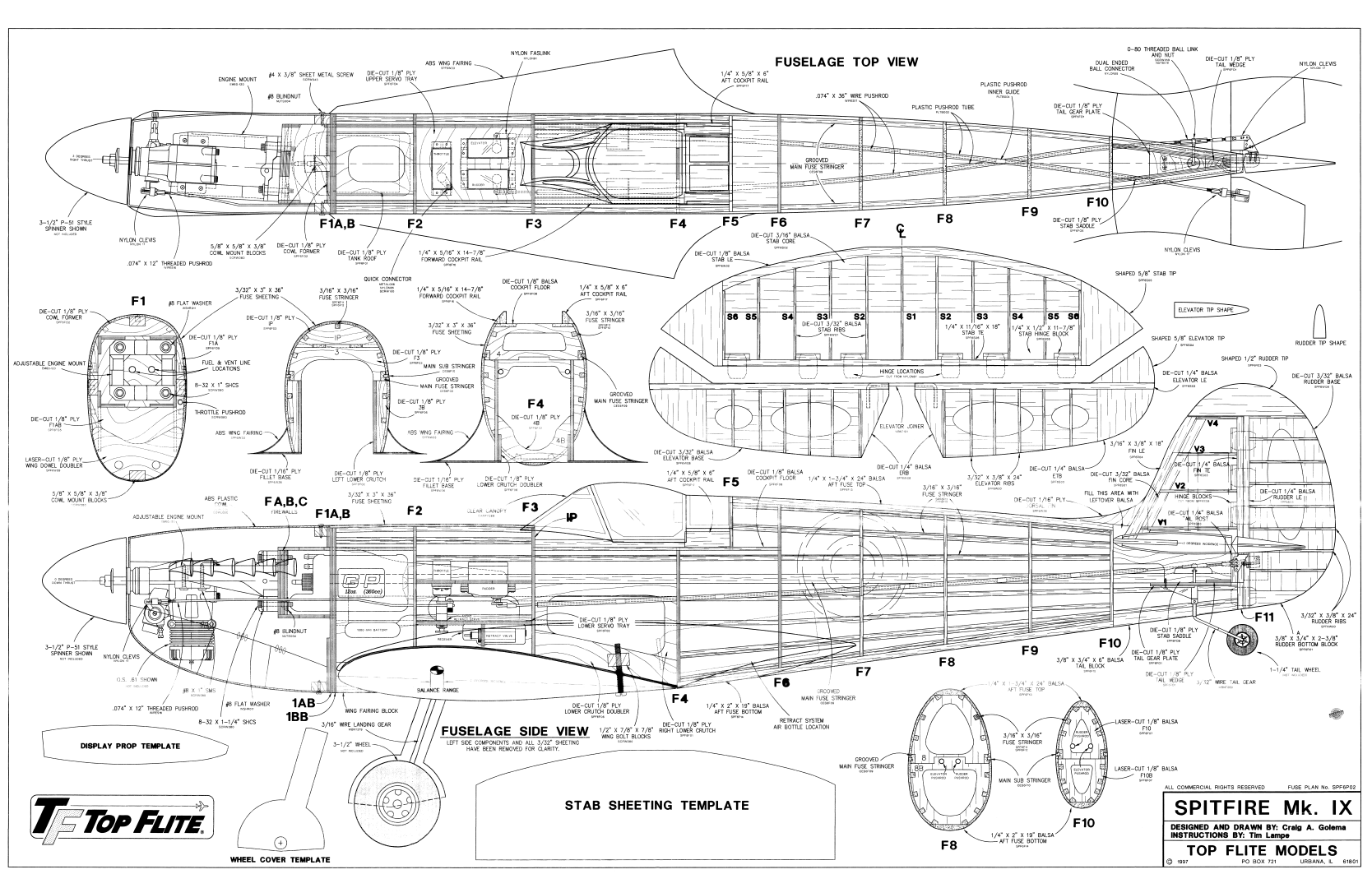
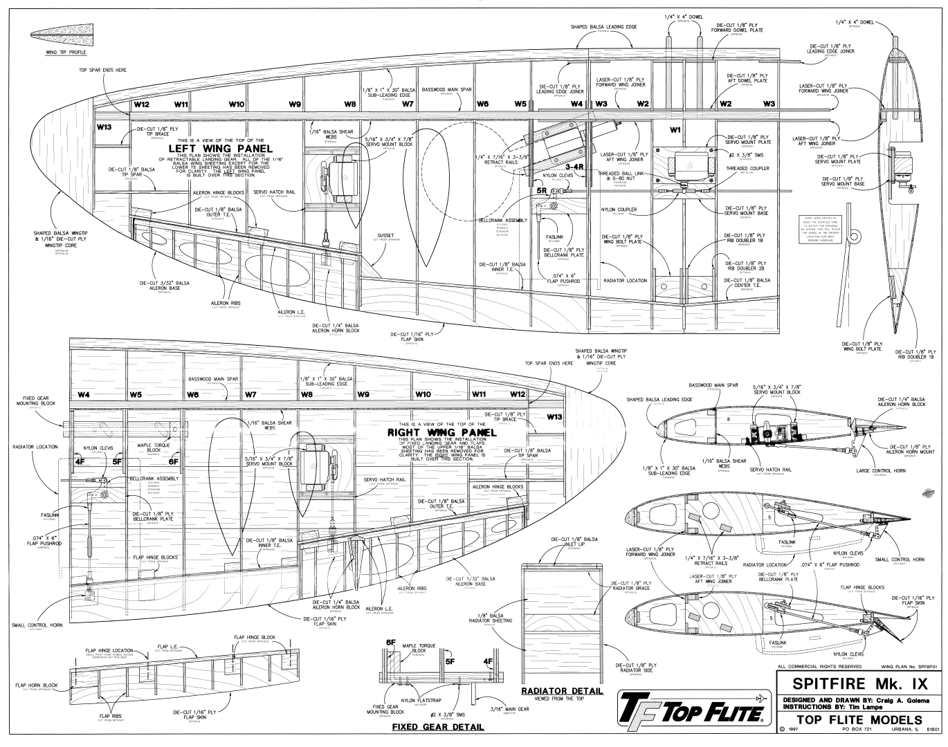
Plan Images are extracts from Top Flite Plans.
RC MODEL CONSTRUCTION: The Top Flite Gold Edition Spitfire model was chosen to replicate the Mk IX — the second most popular Spitfire ever, reaching a total production of 5,665 aircraft. Considered to be the finest Spitfire of all, the Mk IX went into operational service in July, 1942. The RC model was designed and plans drawn by Craig A. Golema, and the instructions are by Tim Lampe.
Craig's plans are full-size, clearly laid out, and give part locations and descriptions. The plans are used in conjunction with a well-illustrated assembly manual into which Tim has obviously put a lot of work into. Included are not only pictures and step-by-step text, but helpful building tips to make the job easier. Everything you need to know is in it. Just to name a few other items needed to complete the model like hardware, building supplies, tools, and a layout of the die-cut parts. Then there are also sections on engine types, retracts, flaps, and even some tips on scale detailing! What more could you ask for!
Recommended engine sizes include .61-.75 cu. in. 2-stroke, or .70-.91 cu. in. 4-stroke. The Spitfire will fly well with any of the recommended engines. The 4-stroke engines and most .75 cu. in. 2-stroke engines will turn a larger prop at lower RPM. This is often desirable for scale realism. Many .61 cu. in. 2-stroke engines produce about as much horsepower as the popular .75 2-stroke engines and will fly the Spitfire extremely well. If you use a .61 2-stroke, a ball bearing, Schnuerle-ported engine is recommended. The prototype Spitfire weighs 9-1/2 pounds with all of the options, including flaps and the scale cockpit interior and was flown with an O.S. .61 cu. in. engine. This engine provided excellent performance and more than enough power. Although larger engines can be used to power this model, the extra horsepower is not needed.
You can build your Spitfire either with fixed or retractable landing gear. Of course, fixed landing gear will be easier to install than retracts; but Top Flite provides detailed instructions on retract installation so you should have no trouble. The Gold Edition Spitfire is designed to accept the Robart #605 90 degree HD (Heavy Duty with 3/16" struts) pneumatic retracts. You may use other retractable landing gear systems but it is up to you to make any modifications that may be necessary. The Spitfire's fuselage is large enough for straight forward radio gear installation and it still allows plenty of room for the optional scale cockpit kit and retract air tank.
The Top Flite Spitfire is designed to incorporate scale split flaps; however, flaps are optional and not necessary for an excellent flying experience. Without flaps, the takeoff roll is longer and the landing speed is faster. The flaps are not difficult to build, but they do require good craftsmanship to fit well. Flaps add nicely to the model's flight characteristics and scale appearance. Only slight trim correction is needed when flaps are used with the recommended throws. Flaps are highly recommended for those who wish to install them.
- RC Model Specifications:
- Aircraft Type: 1/7th Sport Scale Warbird
- Wing Span: 63″
- Total Wing Area: 687 square inches
- Wing loading: 25-28.5 oz/sq. in.
- Wing Location: Low Wing
- Wing Platform: Double Taper
- Fuselage Length: 53″
- Center of Gravity: 4-1/8″ from the leading edge of the wing
- Number of Channels: 4-6 - Throttle, Ailerons, Rudder, Elevator, Flaps, and Retract Gear
- Ready to Fly Weight: 7.5-8.5 lbs. depending on power system selection
- Glow Fuel Engines: .61-.75 cu. in. 2-stroke, or .70-.91 cu. in. 4-stroke
- Electric Powered: Output of 1,200-1,500 Watts, 80 Amp ESC, 6 cell 45C LiPo pack of 5,000mah, and APC 11x7 - 14x7 E-series prop.
The Spitfire Mk IX RC model in this months edition can be built using a set of full-size plans, assembly manual, and review article available @: “Outerzone.”
Outerzone Spitfire Mk IX Webpage.
I hope you have enjoyed this months selection, and just maybe, I have spurred some interest in trying your hand at building an RC model airplane.
Until next month - Keep the Balsa Dust Flying!!
Build of the Month WW-II Mini-Series - January 2025 Edition
I hope you enjoyed last months BOTM WW-II Mini-Series 3rd Edition on the Mitsubishi A6M Zero model. If you have an RC model that you would like to see featured in this section or feel others may find interesting, please let me know and I will make every attempt to find scratch build plans, photos, and maybe even a published build article, which will then post in a future edition. Just send me an email @: Build of the Month.
Ok, now lets see what I have for the month of January 2025. Continuing with the “BOTM WW-II Mini-Series,” for the 4th Edition we will move back to the European Theater and this time on the Eastern Front. How about a fighter that was the single most produced military aircraft design in aviation history. Given these requirements, this 4th Edition of my BOTM WW-II Mini-Series features the Ilyushin IL-2 Stormovik, a fighter manufactured by the Soviet Union.
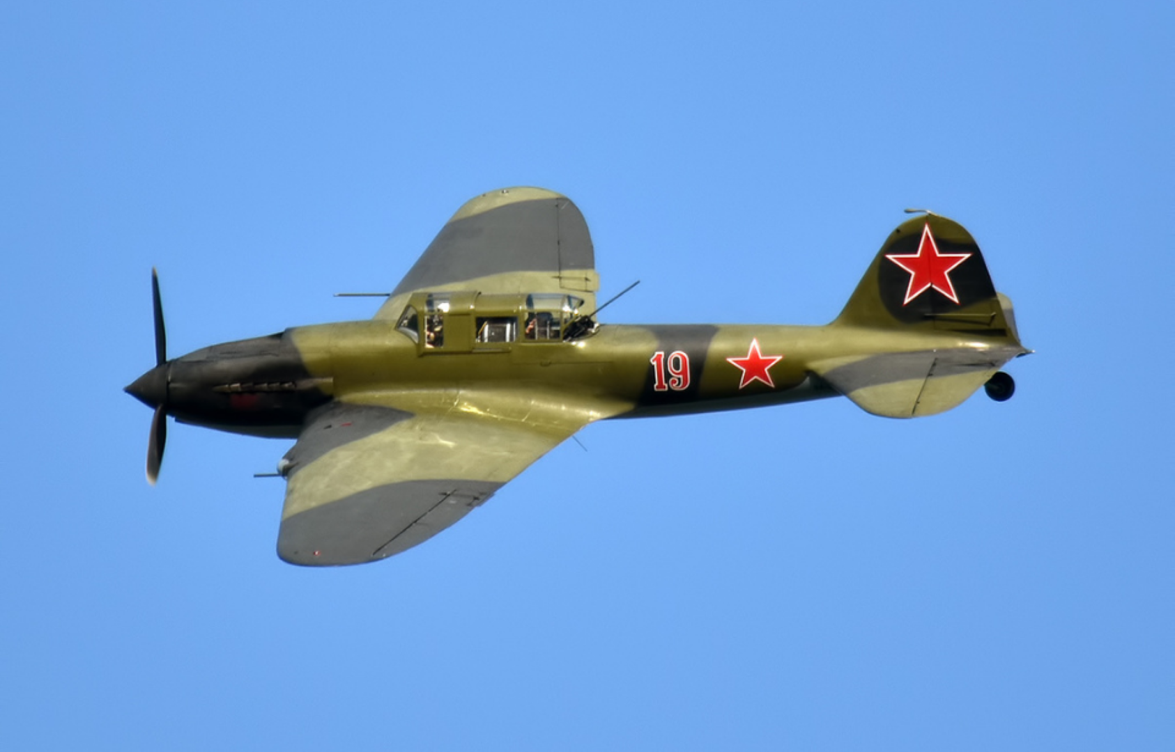
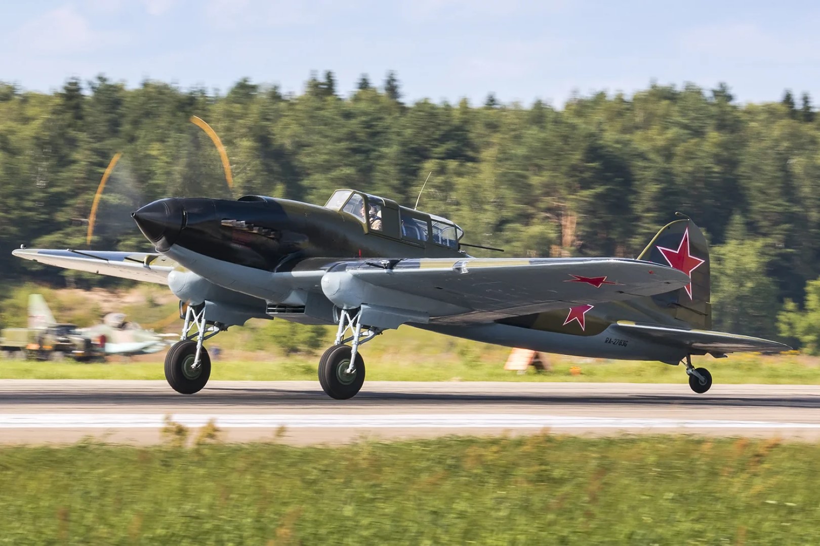
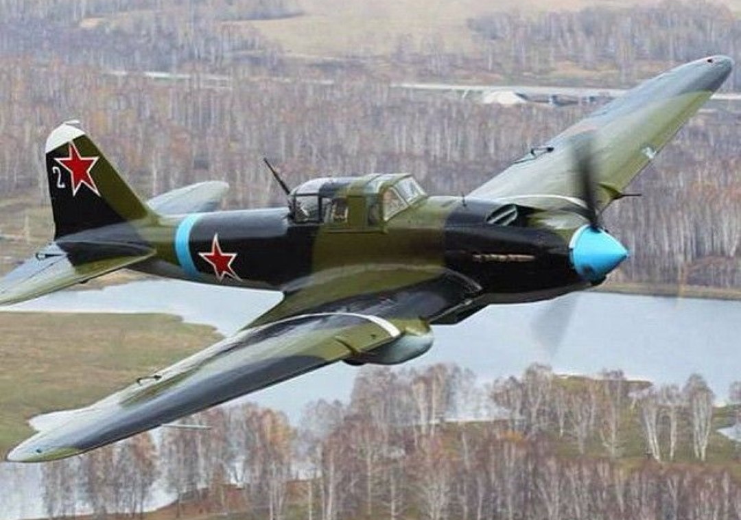
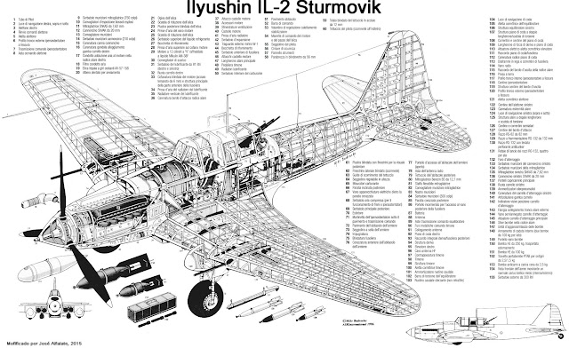
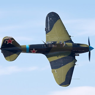
The Ilyushin IL-2 is a ground-attack plane that was produced by the Soviet Union in large numbers during the Second World War. To IL-2 pilots, the aircraft was known by the diminutive "Ilyusha". To the soldiers on the ground, it was called the "Hunchback", the "Flying Tank" or the "Flying Infantryman". Its postwar NATO reporting name was Bark.
The IL-2 was designed by Sergey Ilyushin and his team at the Central Design Bureau in 1938. During the war, 36,183 units of the IL-2 were produced, and in combination with its successor, the Ilyushin IL-10, a total of 42,330 were built, making it the single most produced military aircraft design in aviation history, as well as one of the most produced piloted aircraft in history along with the American postwar civilian Cessna 172 and the German then-contemporary Messerschmitt Bf-109.
The IL-2 played a crucial role on the Eastern Front. When factories fell behind on deliveries, Joseph Stalin told the factory managers that the IL-2s were "as essential to the Red Army as air and bread."
The IL-2 was anything but advanced in its mixed wood-and-metal construction, which was relatively easy to manufacture in significant numbers using relatively unskilled workers. But for an aircraft, it was an amazing achievement. Among the Shturmovik’s most important assets were its strength and robustness in combat. The forward fuselage section, protecting the aircraft’s fuel system, radiators and crew station, was built entirely of armor plate. Thus, the IL-2 could, and often did, absorb extraordinary battle damage and survive to fight another day. The protective armor shell employed a special alloy developed for the IL-2; its thickness varied by location on the airframe. Special consideration had been given to a technology that would allow maintenance personnel to stamp the armor steel in the field, thus providing flexibility in the design, especially when Soviet units were forced to operate from primitive forward battle areas.
The IL-2 continued in service into the Cold War period (1947-1991) where it was delivered to Soviet allies across Europe. Bulgaria took on a fleet of 120 IL-2 attackers and 10 IL-2U trainers in 1934 and operated these well into 1954. Similarly, the IL-2 formed a portion of the Hungarian Air Force, and these were flown into 1952. Czechoslovakia took on 33 IL-2 attackers and 2 trainer forms for their part and operated them during the war in 1944 into 1949. Mongolian Army Aviation fielded 71 IL-2 aircraft from 1945 onwards and actively supported them into 1954. Yugoslavia fielded the IL-2 in no fewer than ten Air Force squadrons - the last ones were retired in 1954.
The legacy of the IL-2 lives on today in the Sukhoi Su-25 "Frogfoot", the Soviet answer to the American Fairchild Republic A-10 "Thunderbolt II" (Warthog). Like the IL-2, the Su-25 bristles with a broad armament array (missiles, rockets, gunpods and the like), is developed for low-altitude fighting, and has survivability features such as an ejection seat, twin-engine configuration, and armored systems and sub-systems not to mention active and passive warning and countermeasures systems.
- Actual Aircraft Specifications:
- Crew: Two
- Length: 11.65 m (38 ft 3 in)
- Wingspan: 14.60 m (47 ft 11 in)
- Height: 4.17 m (13 ft 8 in) (tail up)
- Wing area: 38.50 m2 (414.4 sq ft)
- Empty weight: 4,425 kg (9,755 lb)
- Max takeoff weight: 6,360 kg (14,021 lb)
- Power plant: 1 – Mikulin AM-38F liquid-cooled V12 engine, 1,280 kW (1,720 hp) (takeoff power), 1,100 kW (1,500 hp) at 750 m (2,460 ft)
- Propellers: 3-bladed AV-57-158 variable-pitch propeller, 3.60 m (11 ft 10 in) diameter
- Maximum speed: 410 km/h (250 mph, 220 kn) at 1,500 m (4,900 ft)
- Range: 765 km (475 mi, 413 nmi) at 275 km/h (171 mph; 148 kn) and 1,000 m (3,300 ft)
- Service ceiling: 4,525 m (14,846 ft) (service ceiling), 6,360 m (20,870 ft) (absolute ceiling)
- Guns: 2 – fixed forward-firing VYa-23 cannons, 150 rounds per gun
- 2 – fixed forward-firing ShKAS machine guns, 750 rounds per gun
- 1 – manually aimed Berezin UBT machine gun in rear cockpit, 300 rounds
- Rockets: 8 – RS-82 rockets or 4 – RS-132 rockets
- Bombs: 6 – 100 kg (220 lb) bombs in wing bomb-bays and underwing, or 4 – dispensers for 48 – 2.5 kg (5.5 lb) PTAB anti-armour bombs (192 total) in wing bays
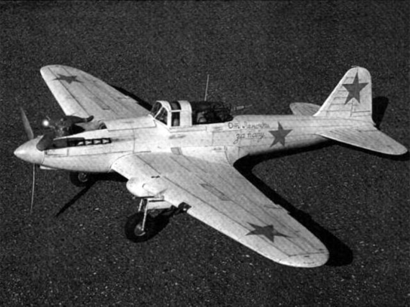
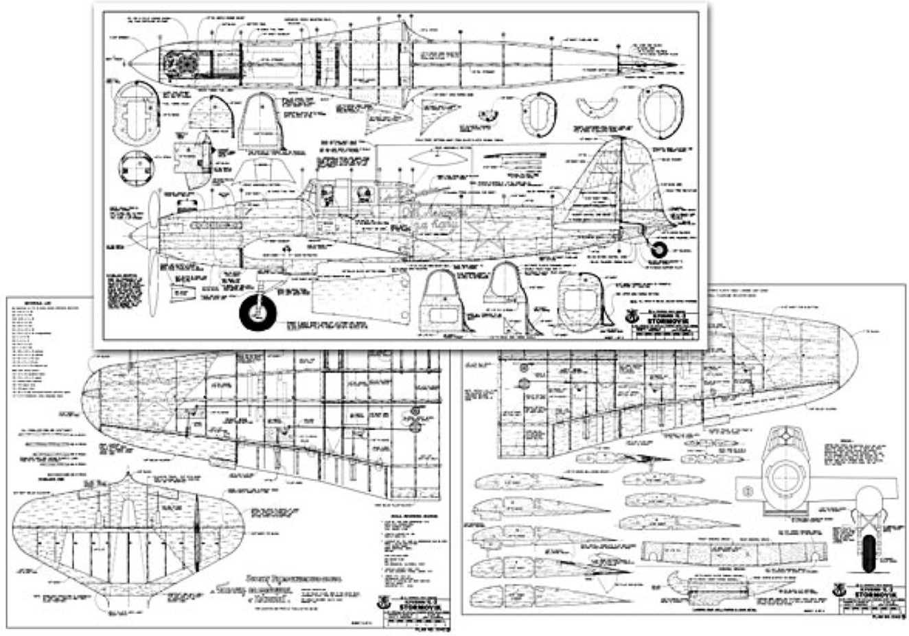

Source of Images: Outerzone Ilyushin IL-2 Stormovik Webpage.
RC MODEL CONSTRUCTION: The Stormovik was as important to Russia as the Spitfire was to Great Britain and the Mustang was to America, yet the Stormovik is not well known in the West. Perhaps we modelers can do something about that. As a scale model, the Stormovik has excellent moments. It has a high-lift airfoil, a long, slender fuselage, a huge tail, and short, wide-apart landing gear with big wheels. The full-size Stormovik was designed for rough-field operation and low-speed stability - just the qualities we seek in a scale subject.
It's odd that it is rarely seen in model form; the only other RC design I know of is Bob Underwood's version which placed in the AMA Nats in the early 80s. The Stormovik presented here was prepared by photo-enlarging the Aeromodeler/MAP drawings and filling in the structure. It is exact; no deviations from scale were permitted. If you use the Aeromodeler drawings for “proof of scale” documentation and you follow the plans faithfully, you should receive a perfect score for “accuracy of outline” in AMA scale contests. Only part of the Aeromodeler drawing is presented here; the complete drawing contains additional views and more detail. The Profile publication number 88 is apparently derived from the same Aeromodeler drawing, so it is also excellent scale documentation plus it contains many color schemes.
Upgrading to Precision Scale or FAI scale is possible by adding more details. If you decide to build this airplane, you should first gather all scale documentation before cutting the first piece of wood (see the list of references on the plans). Then, wait for a cold Siberian night, put on your boots and babushka, and march down to your shop. Shove a tape of Shostikovitch's Leningrad Symphony into the stereo and toast a “salut” to Mother Russia. Let's begin..."
WING: Wing construction starts with making wing ribs. It is important to drill the 1/4″ wing rod holes as accurately as possible. Don't drill these holes with a twist drill, it will tear balsa wood instead of cutting it, and it does not permit accurately centering the drill. Here is a better way to do it. Cut a 3/4″ section of 1/4″ O.D. brass tube. Bevel the inside edge of one end with a Dremel grinding stone. Grind the edge to be as sharp as possible. Chuck this in your drill press or electric hand drill. Place a wing rib on a flat piece of pine and slip it under the drill press. Lower the brass tube, motor off, until the tube touches the 1/4″ circle marked on the rib. Align to a perfect match and turn on the drill. Lower the tube slowly until resistance is felt and withdraw. Voila! - a perfect hole. Remove the tube and push out the balsa plug. Resharpen after every 10 holes.
The wing is built on a wing jig, one panel at a time. If you have a commercial wing jig, use it. Otherwise, buy two 3′, 1/4″ steel rods from the local hardware store. Apply a very thin coat of oil to the rods, just in case some glue spills on them. Lay these over the wing plan, raised on short sections of wooden blocks beyond the root rib and tip rib. The image below shows my wing jig being used to build a Bokkie wing. It works GREAT! You can build the same wing jig using the August 1967 RCM Article available @: RCBookcase.com.
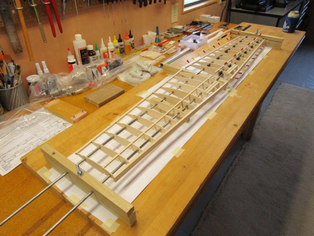
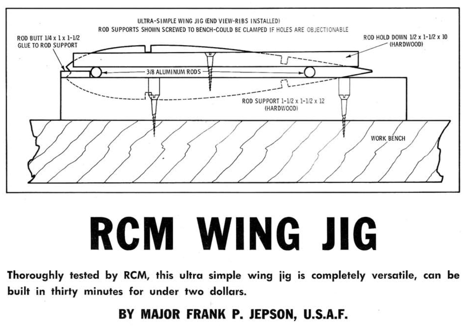
FUSELAGE: The fuselage structure is “flat sides and formers” typical of pattern ships and non-scale airplanes. Use light materials for everything aft of the Center of Gravity and hollow the tail blocks to save weight. Use only 4-6 pound grade balsa. Remember that any unnecessary weight in the tail must be paid for by 6 times as much counterweight in the nose, and all unnecessary weight degrades performance.
FLIGHT CHARACTERISTICS: Check and double-check the balance point (C.G.) as shown on the plans. Further forward is okay, but don't let the C.G. be aft of this point. If the plane turns out to be considerably heavier than 9 pounds, the C.G. should be even further forward. Ground handling is outstanding. No up elevator is required for starting the take-off roll, just hit the loud-lever and steer with the rudder. When properly trimmed, it will lift off by itself. Good ground handling is to be expected, considering the rough field conditions for which the original was designed.
The plane is quite stable and very smooth flying. Slow rolls are axial and uniform in roll rate. Low passes are chilling, this is the airplane that destroyed 70 German tanks in 20 minutes. When you see those cannon barrels coming at you and you hear the engine snarling, remember that the German Army called this airplane Schwarz Tod — “Black Death.” The flaps are very effective. Steep descents for landing with full flap cause no buildup in airspeed. 40 degrees of flap is about right for a normal landing approach or for slow fly-bys. This permits slow flight without loss of stability. But full flap should be used only in steep descents, they slow the airplane too much in level flight. The stronger the wind, the less flap deflection. If the wind is greater than 15 mph, don't use any flap at all for landings. Never use flaps for take-offs except, perhaps, partial flap in dead-calm air.
Spins are slow with no tendency to become flat. Neutralizing the rudder and elevator instantly stops the spin. At the elevator throw shown on the plans, entry to the spin is critical. If you wish to do spins as a contest maneuver, you must use greater elevator throw for more reliable spin entrance, a good application for dual rates.
- RC Model Specifications:
- Aircraft Type: Sport Scale Warbird
- Wing Span: 70″
- Wing Chord: 18″ Root, 7″ Tip
- Total Wing Area: 880 square inches
- Wing Location: Low Wing
- Airfoil: 14 percent Scale Flat Bottom
- Wing Platform: Double Taper
- Dihedral each Tip: 2″
- Fuselage Length: 58″
- Stabilizer Span: 25″
- Stabilizer Chord (including elevator): 9″
- Total Stab Area: 235″
- Number of Channels: 6 - Throttle, Ailerons, Rudder, Elevator, Flaps, and Retract Gear
- Ready to Fly Weight: 144 oz. depending on power system selection
- Glow Fuel Engines: .90 - 1.08 2-stroke or 1.2 4-stroke
- Electric Powered: Output of 1,800-2,400 Watts, 80-120 amp ESC, 4-6 cell 45C LiPo pack of 5,000mah.
The Ilyushin IL-2 Stormovik RC model in this months edition can be built using a set of plans and article which are available @: “Outerzone.”
Outerzone Ilyushin IL-2 Stormovik Webpage.
I hope you have enjoyed this months selection, and just maybe, I have spurred some interest in trying your hand at building an RC model airplane.
Until next month - Keep the Balsa Dust Flying!!
 All HTML & CSS Coded by Larry