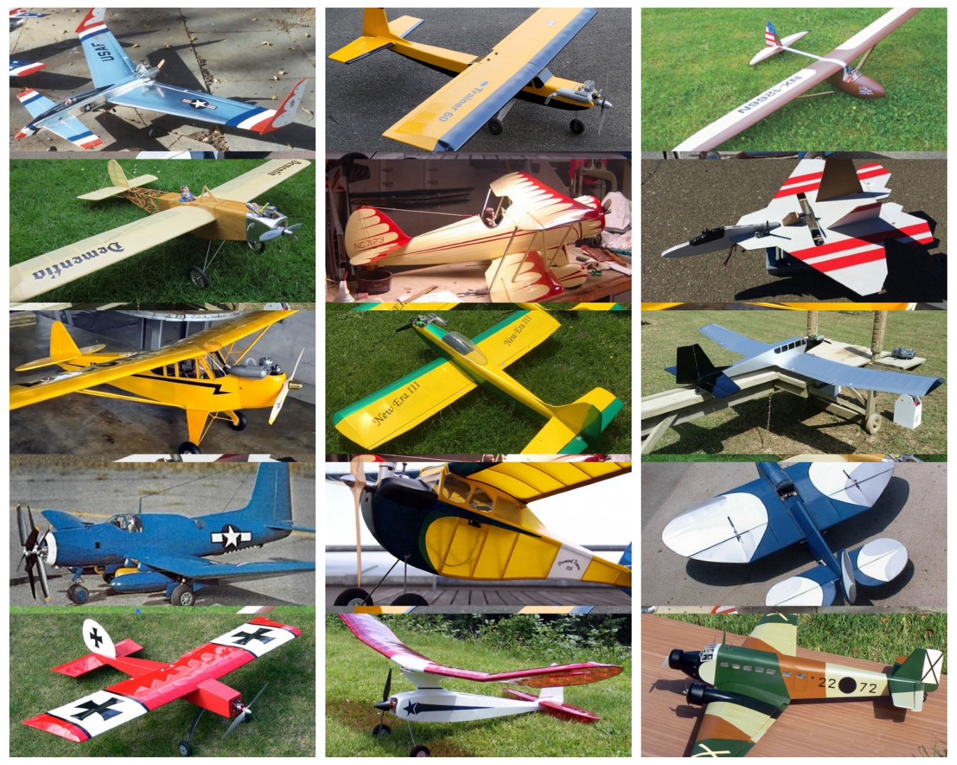

For visitors to my website, my “Build of the Month” (BOTM) Series was created to help those who are trying to get started in building their own Radio Controlled (RC) Model Aircraft.
"Aerofred.com" and "Outerzone.co.uk" are two of my favorite web sites to obtain free RC model airplane plans for my new builds. Additionally, they like to post images of Builder's models, and both sites have posted my RC model images and build descriptions under the heading of the associated aircraft model. Other good sources for free plans are: "Hip Pocket Aeronautics Builders' Plan Gallery", "Vintage & Old-Timer RCM Free Plans", "James Hatton Blog Free Plans and Articles", "Hlsat Blog RCModeler Free Plans and Articles", and "Don Dewey Memorial RCM Plans Collection."
If you are currently not an active builder, and you would like to be, my BOTM Series is a great place to start. If you have an RC model aircraft that you would like to see featured in this section or feel others may find interesting, please let me know and I will make every attempt to find scratch build plans, photos, and maybe even a published build article, which I will then post in a future BOTM edition. Just send me an email @: Build of the Month.
Click on any link below to jump to that BOTM Edition
March 2025 — De Havilland DH 98 Mosquito
February 2025 — Supermarine Spitfire
January 2025 — Ilyushin IL-2 Stormovik
December 2024 — Mitsubishi A6M Zero
November 2024 — Bell P-39 Airacobra
October 2024 — Junkers Ju-52/3m
September 2024 — Playboy Senior
August 2024 — Das Ugly Stik
NOTE - You can view all images in a “Spotlight Box” by simply clicking on any image.
Build of the Month WW-II Mini-Series - March 2025 Edition
I hope you enjoyed last months BOTM WW-II Mini-Series 5th Edition on the Supermarine Spitfire model. If you have an RC model that you would like to see featured in this section or feel others may find interesting, please let me know and I will make every attempt to find scratch build plans, photos, and maybe even a published build article, which will then post in a future edition. Just send me an email @: Build of the Month.
Ok, now lets see what I have for the month of March 2025. Continuing with the “BOTM WW-II Mini-Series,” for the 6th Edition we will look at a fighter that served in Europe, the Mediterranean, and the Pacific. Lets find a fighter that is a twin-engined, multi role combat aircraft, and unusual in that its airframe is constructed mostly of wood. So given these requirements, this 6th Edition of my BOTM WW-II Mini-Series features the De Havilland DH 98 Mosquito, a fighter manufactured by Great Britain.
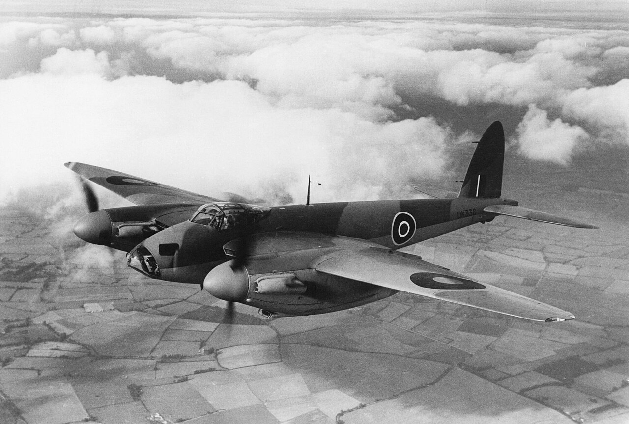
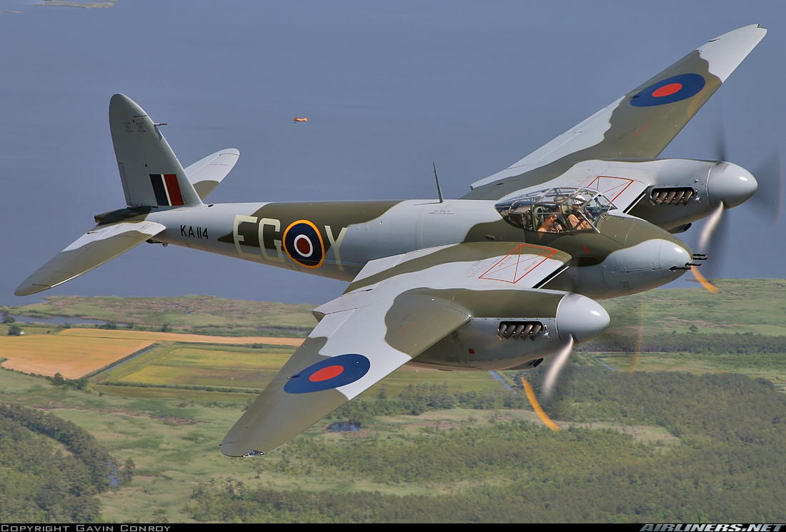
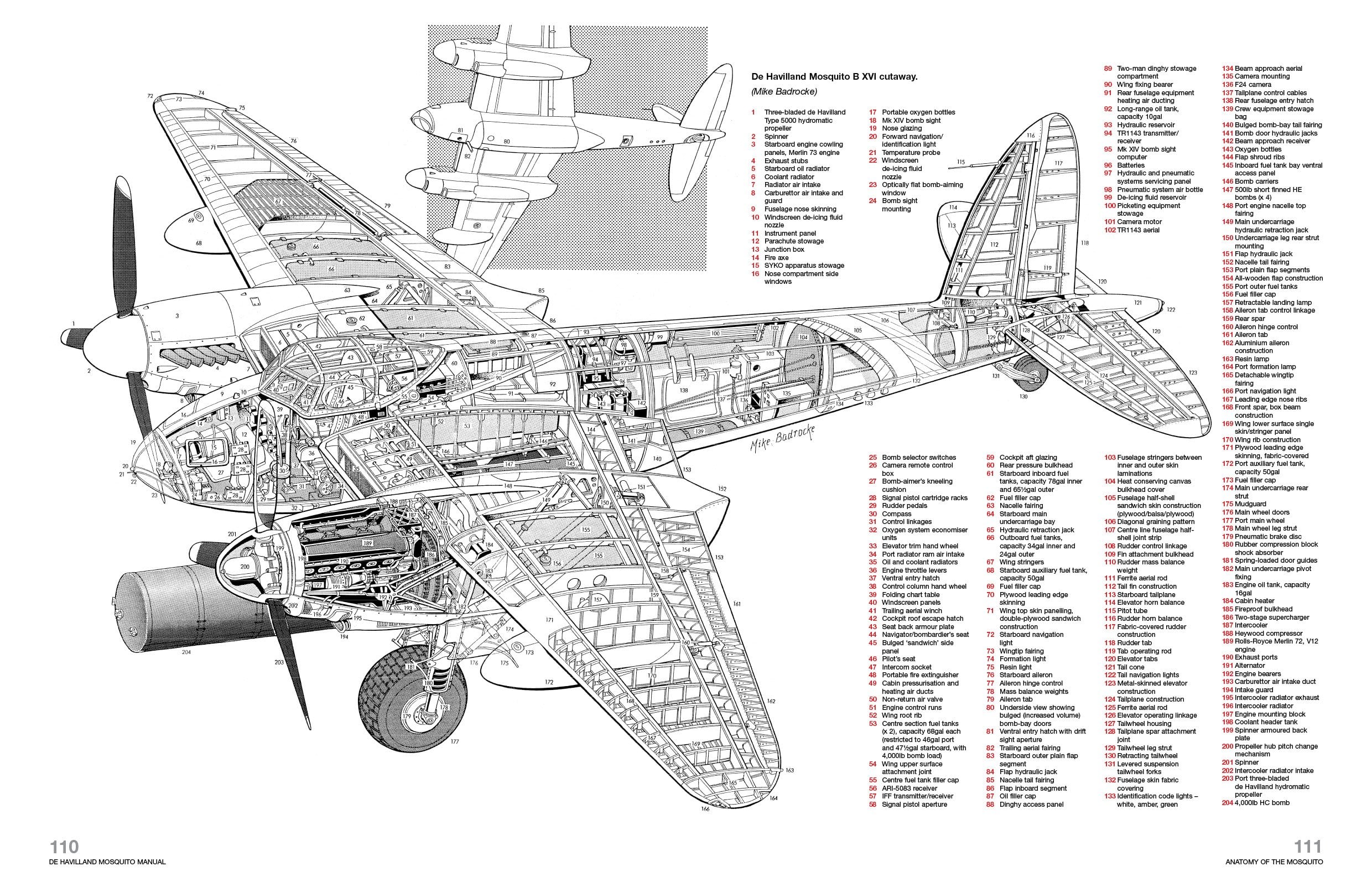
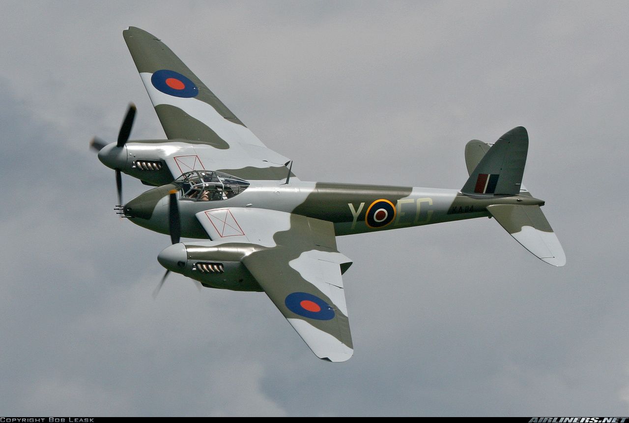
The De Havilland DH 98 Mosquito is a British twin-engined, multi role combat aircraft, introduced during the Second World War. De Havilland's design of the Mosquito came about when Britain needed a cheap, easy to build, and capable bomber. Unusual in that its airframe was constructed mostly of wood, which sped up the manufacturing process, it was nicknamed the “Wooden Wonder”, or “Mossie”. In 1941, it was one of the fastest operational aircraft in the world. Many allied and enemy airplane manufacturers sneered at the idea when the Mosquito was conceptualized, with many calling it a large model airplane.
Officials in the British Air Ministry vehemently resisted building it, but from the day production finally began in 1941 until the war ended, the Royal Air Force (RAF) never had enough Mosquitoes to perform the amazing variety of missions that air tacticians devised for this outstanding airplane. It excelled at day and night bombing from high or very low altitudes, long-range reconnaissance, air-to-air combat in daylight and darkness, and finding and striking distant targets at sea. No less than forty-two distinct versions of the DH 98 entered service. At extreme speeds, Mosquitoes carried heavy loads great distances because of two key design features: a lightweight, streamlined, wooden airframe propelled by powerful, reliable engines. The “Wooden Wonder” was constructed from Alaskan spruce, English ash, Canadian birch and fir, and Ecuadorian balsa glued and screwed together in new, innovative ways, and motivated by the world's finest reciprocating, liquid-cooled power plants, a pair of Rolls Royce Merlins. There has never been a more successful, combat-proven warplane made of wood.
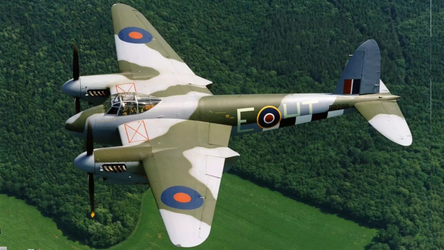
Like the Comet and Albatross wings, De Havilland built Mosquito wings out of shaped pieces of wood and plywood cemented together with Casein glue. Approximately 30,000 small, brass wood screws also reinforced the glue joints inside a Mosquito wing (another 20,000 or so screws reinforced glue joints in the fuselage and empennage). The internal wing structure consisted of plywood box spars fore and aft. Plywood ribs and stringers braced the gaps between the spars with space left over for fuel tanks and engine and flight controls. Plywood ribs and skins also formed the wing leading edges and flaps but De Havilland framed-up the ailerons from aluminum alloy and covered them with fabric. Sheet metal skins enclosed the engines and metal doors closed over the main wheel wells when the pilot retracted the landing gear.
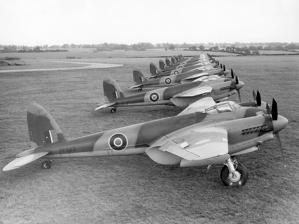
The Mosquito flew with the RAF and other air forces in the European, Mediterranean, and Italian theaters. The Mosquito was also operated by the RAF in the Southeast Asian theater and by the Royal Australian Air Force based in the Halmaheras and Borneo during the Pacific War. During the 1950s, the RAF replaced the Mosquito with the jet-powered English Electric Canberra. The Mosquito was a highly successful plane, serving the RAF in various roles. The plane’s high speed of 668 km/h and agility made it a difficult target for the enemy to shoot down. Not bad for a life-sized toy airplane!
The Mosquito flew its last war mission on May 21, 1945, searching for German submarines in waters off the coast of Scotland. In total, between 1940 and 1950, the total number of DH 98 Mosquito aircraft built was 7,781, and were manufactured in the United Kingdom, Canada, and Australia. The type serving with the main Allied air forces, including both the United States and Russia and postwar many were operated by the air forces of France, Belgium, Turkey, Sweden, Dominica, South Africa, Yugoslavia, Australia, Canada, China, Czechoslovakia, Israel, New Zealand and Norway.
- Actual Aircraft Specifications:
- Crew: Two: pilot, bomb aimer/navigator
- Length: 44 ft 6 in (13.56 m)
- Wingspan: 54 ft 2 in (16.51 m)
- Height: 17 ft 5 in (5.31 m)
- Wing area: 454 sq ft (42.2 m2)
- Empty weight: 14,300 lb (6,486 kg)
- Max takeoff weight: 25,000 lb (11,340 kg)
- Power plant: 2 – Rolls-Royce Merlin V-12 liquid-cooled piston engine, 1,710 hp (1,280 kW) each -76 driving the left propeller, -77 driving right
- Propellers: 3-bladed constant-speed propellers
- Maximum speed: 415 mph (668 km/h, 361 kn) at 28,000 ft (8,500 m)
- Range: 1,300 mi (2,100 km, 1,100 nmi)
- Service ceiling: 37,000 ft (11,000 m)
- Rate of climb: 2,850 ft/min (14.5 m/s)
- Guns: 4 – 7.7 mm Browning machine guns, 4 – 20 mm Hispano cannons
- Bombs: 4,000 lb (1,800 kg)
Images above were found online @: Outerzone Mosquito Webpage, extracted from article in July 1983 Model Aviation Magazine, and a Bing Search.
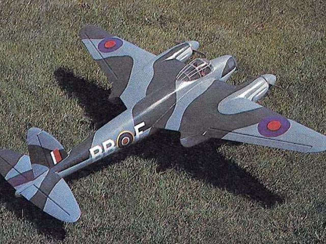
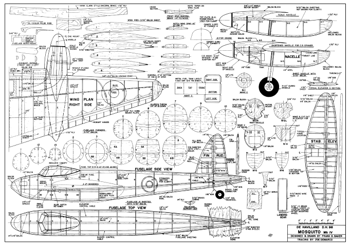
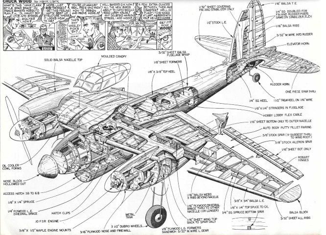
Please note - Much of the following description was extracted from an article written by Frank B. Baker and published in the July 1983 issue of Model Aviation Magazine. The De Havilland DH 98 Mosquito MK IV plans were also designed and drawn by Frank.
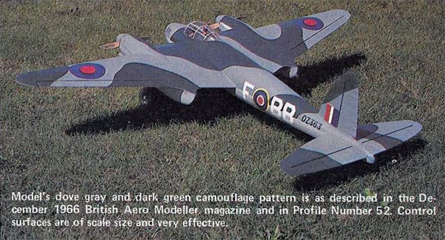
The Mosquito is one of the few full-sized aircraft that, when photographed, looks like a model airplane. This is due, in part, to its plywood and balsa construction that results in an exceptionally smooth exterior surface. Modelers seem to have a special affinity for this aircraft. Maybe it is because so much balsa was used in its construction. Frank started from a set of excellent drawings that appeared in the December 1966 issue of Aeromodeller. His DH 98 RC model is 1/12th scale and was designed for OS Max .10FSR engines, uses four-channel controls, and it flies perfectly at a weight of 4-1/2 pounds. It's to scale except for the out-thrusted nacelle's, a feature which gives the model amazing one-engine-out performance.
RC MODEL CONSTRUCTION: While not difficult, the Mosquito must be built in the proper order. Since this model is not for a beginner, Frank does not give a step-by-step account in his article, but he does highlight some of the major things that must be done in proper sequence, as well as, some of the innovations. His article build description starts with the wing, followed by the fuselage, engine nacelles, tail surfaces, and then finishing. This is a fairly straight forward scratch built balsa and ply RC model. Lots of ribs of varying sizes, 13 formers in the fuselage, and 7 more formers in each engine nacelle. But, that is what we “scratch builders” like, right!!
FLIGHT CHARACTERISTICS: Frank reminds his readers that this is a Scale model, and it must be flown with respect. On takeoffs the tail will lift rather quickly, but do not break ground until a lot of speed has been built up. Then use just enough elevator to lift off and climb at a modest angle of attack. Once airborne, the Mosquito is quite fast. The narrow, pointed tips make it quite sensitive to ailerons. This is especially noticeable at higher speeds. Experiment with throws until the ailerons are effective without being sudden. Landings are really fun. Set up a long, flat approach, and control the descent with the throttle. I let it keep flying in a level attitude until the wheels touch, and then I go to full engine idle. The single-engine performance is outstanding. On several flights Frank states he has lost one engine and did not realized it until on final, where he could see the stopped propeller.
A FINAL CAUTION: The gray color and the camouflage is quite effective, and it is easy to lose orientation if the plane gets too far out. Frank punched-in his Mosquito once due to visual mis-orientation and hardly scratched the plane. Keep your Mosquito RC model close. It is a lot prettier up close, and you can see what you are doing. Overall, the Mosquito is a very smooth flying model, and it looks very scale like in the air. One recommendation is to install retracts. What a sight that would be in the air!
- De Havilland DH 98 Mosquito RC Model Specifications:
- Aircraft Type: 1/12th Scale Warbird
- Wing Span: 54″
- Wing Chord: 14″ Root, 4″ Tip
- Total Wing Area: 486 square inches
- Wing Location: Mid-Wing
- Wing Platform: Double Taper
- Fuselage Length: 42″
- Stabilizer Span: 22″
- Stabilizer Chord (including elevator): 6″
- Number of Channels: 4 - Throttle, Ailerons, Rudder, Elevator
- Ready to Fly Weight: 4.5 lbs. depending on power system selection
- Glow Fuel Engines: Two .10 2-stroke
- Electric Powered: Output of 200-300 Watts each, 30-40 Amp ESC's, 3 cell 45C LiPo pack of 3,000-4,000mah.
The De Havilland DH 98 Mosquito MK IV RC model in this months edition can be built using a set of plans and article available @: “Outerzone.”
July 1983 Issue of Model Aviation Magazine.
December 1966 Issue of Aeromodeller.
I hope you have enjoyed this months selection, and just maybe, I have spurred some interest in trying your hand at building an RC model airplane.
Until next month - Keep the Balsa Dust Flying!!
Build of the Month WW-II Mini-Series - February 2025 Edition
I hope you enjoyed last months BOTM WW-II Mini-Series 4th Edition on the Ilyushin IL-2 Stormovik model. If you have an RC model that you would like to see featured in this section or feel others may find interesting, please let me know and I will make every attempt to find scratch build plans, photos, and maybe even a published build article, which will then post in a future edition. Just send me an email @: Build of the Month.
Ok, now lets see what I have for the month of February 2025. Continuing with the “BOTM WW-II Mini-Series,” for the 5th Edition we will look again at the European Theater but this time on the Western Front. How about a fighter that was the best-known British airplane of WW-II. So given these requirements, this 5th Edition of my BOTM WW-II Mini-Series features the Supermarine Spitfire, a fighter manufactured by Great Britain.
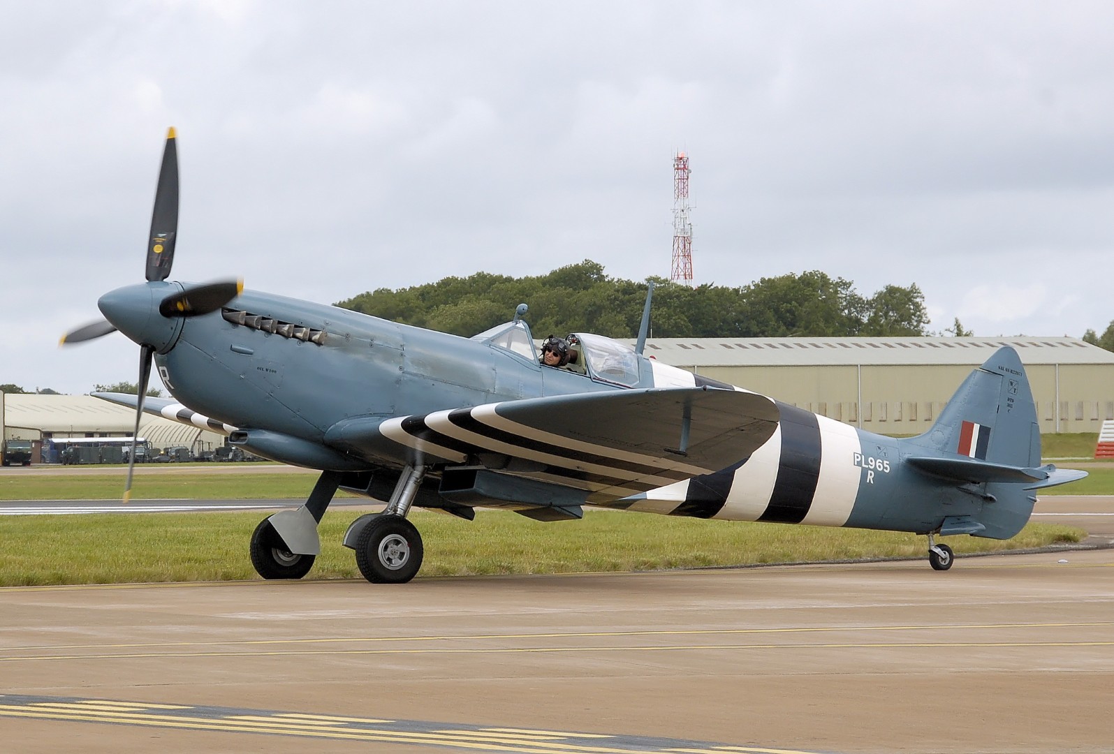
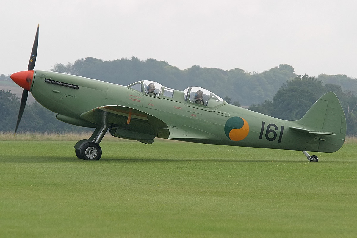
Images Source: Wikipedia Spitfire Webpage.
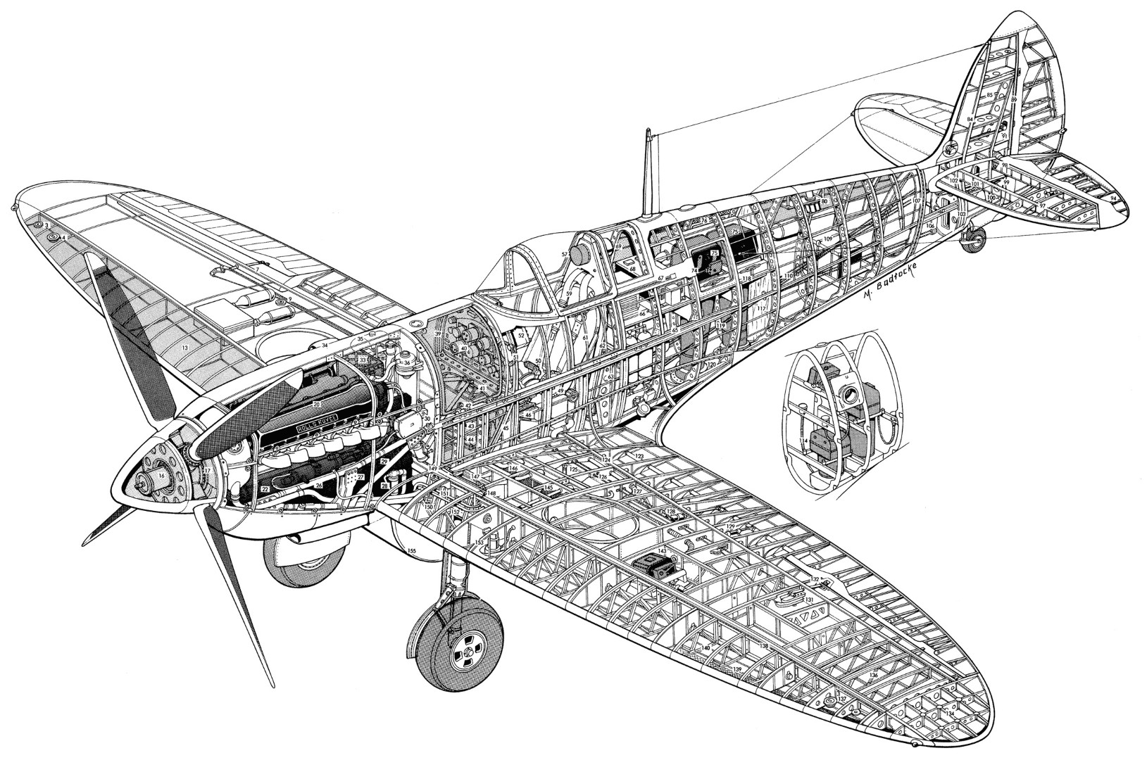
Image Source: An Illustrated Anatomy Of the World’s Fighters.
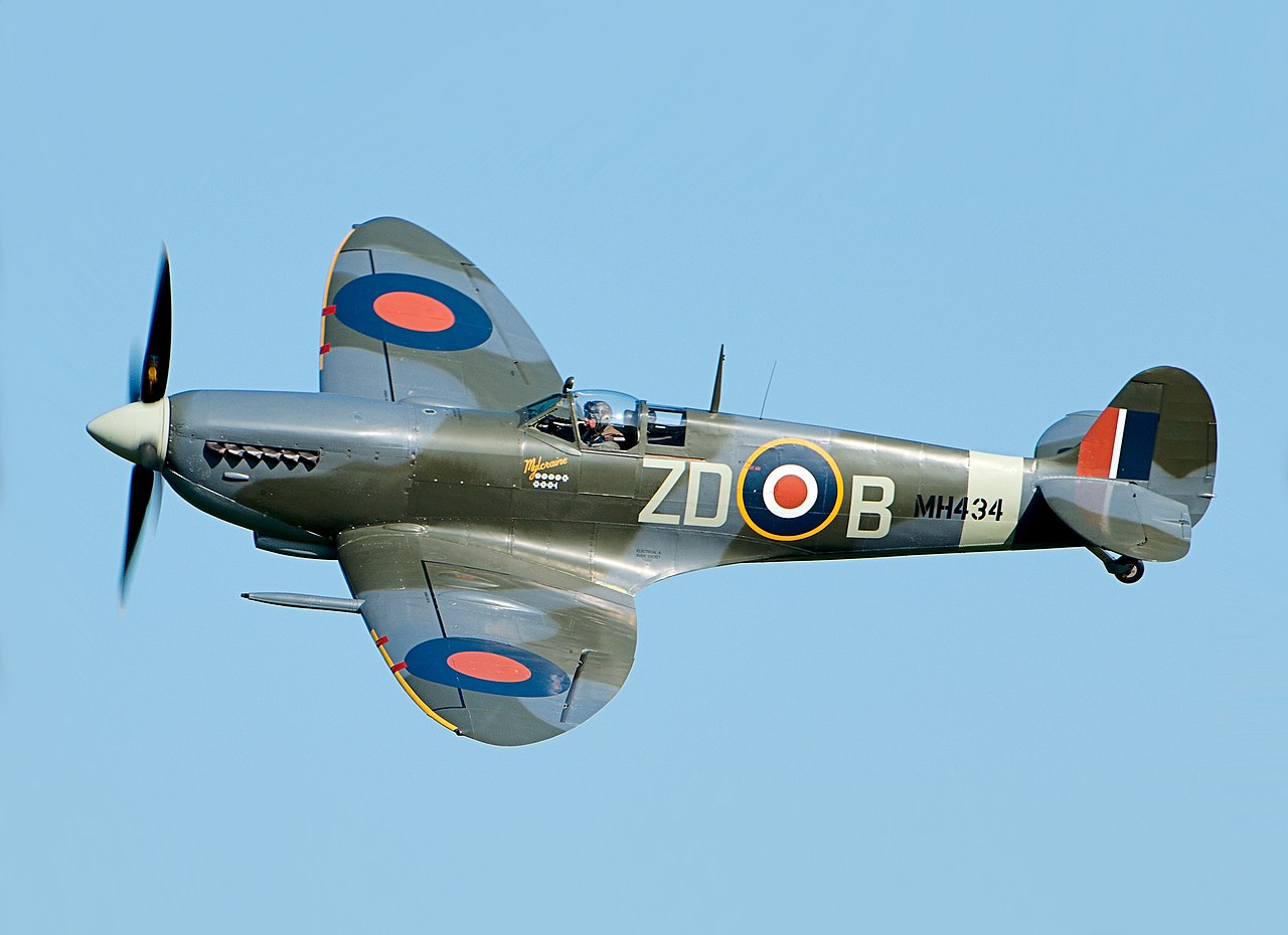
The Supermarine Spitfire is a British single-seat fighter aircraft used by the Royal Air Force (RAF) and other Allied countries before, during, and after World War II. It was the only British fighter produced continuously throughout the war. The Spitfire remains popular among enthusiasts.
The Spitfire was designed as a short-range, high-performance interceptor aircraft by R. J. Mitchell, chief designer at Supermarine Aviation Works, which operated as a subsidiary of Vickers-Armstrong from 1928. Mitchell developed the Spitfire's distinctive elliptical wing (designed by Beverley Shenstone) with innovative sunken rivets to have the thinnest possible cross-section, achieving a potential top speed greater than that of several contemporary fighter aircraft, including the Hawker Hurricane. Mitchell continued to refine the design until his death in 1937, whereupon his colleague Joseph Smith took over as chief designer.
The Spitfire is notable for its sleek, slender body, which allowed a maximum speed of 580 km/h. It’s also famous because its design and aerodynamic capabilities allowed it to sustain damage and remain in the air. This allowed pilots to withstand a beating during combat and keep on fighting, much to the enemy’s frustration.
Developed in 1938, the Spitfire was kept under wraps during the start of WW-II, with the Hawker Hurricane doing most of Britain’s aerial bidding. Soon, it became clear that the Hurricane was no match for German air superiority, forcing them to try the Spitfire. It did not disappoint!
In addition to its design, the power of the Spitfire was unmatched during WW-II. It had 8 machine guns mounted to deliver a rain of fire to bombers and ground targets alike. It was among the only airplanes that could seriously challenge the aerial superiority of the German juggernaut, the Messerschmitt Bf-109.
During the Battle of Britain, the more numerous Hurricane flew more sorties resisting the Luftwaffe, but the Spitfire captured the public's imagination as the main RAF fighter, in part because the Spitfire was generally a better fighter aircraft than the Hurricane. Spitfire units had a lower attrition rate and a higher victory-to-loss ratio than Hurricanes, most likely due to Spitfire’s higher performance. During the battle, Spitfires generally engaged Luftwaffe fighters, mainly Messerschmitt Bf 109E–series aircraft, which were a close match for them.
The Spitfire reigned the skies during the Battle of Britain as it shot down 529 enemy aircraft, effectively regaining allied control of the air and keeping Britain in the war. It went on to succeed further afield from Europe to the Mediterranean and Pacific theaters of war. In all, over 20,000 Spitfires were built in different variants.
Owing to its wide usage in WW-II and iconic status, many Spitfires have survived into preservation. Some 240 Spitfires are preserved as of 2023; this includes around 60 which are airworthy. Many air museums have Spitfires on static display, for example, Chicago's Museum of Science and Industry has paired a static Spitfire with a static Ju 87 R-2/Trop Stuka dive bomber.
- Supermarine MK 24 Spitfire Aircraft Specifications:
- Crew: One
- Length: 29 ft 11 in (9.12 m)
- Wingspan: 36 ft 10 in (11.23 m)
- Height: 11 ft 5 in (3.48 m)
- Wing area: 242.1 sq ft (22.49 m2)
- Empty weight: 5,065 lb (2,297 kg)
- Max takeoff weight: 6,700 lb (3,039 kg)
- Power plant: 1 – Rolls-Royce Merlin 45 V-12 liquid-cooled piston engine, 1,470 hp (1,100 kW)
- Propellers: 3-bladed Rotol constant-speed propeller
- Maximum speed: 370 mph (600 km/h, 320 kn)
- Range: 479 mi (771 km, 416 nmi)
- Combat range: 248 mi (399 km, 216 nmi)
- Ferry range: 1,100 mi (1,800 km, 960 nmi) with fuel tank
- Service ceiling: 36,500 ft (11,100 m)
- Rate of Climb: 2,600 ft/min (13 m/s)
- Guns: 2 – 20 mm Hispano Mk II cannon (120 rounds per gun)
- 2 – .50 in M2 Browning machine guns (250 rounds per gun)
- Rockets: 2 RP-3 rockets (1 under each wing)
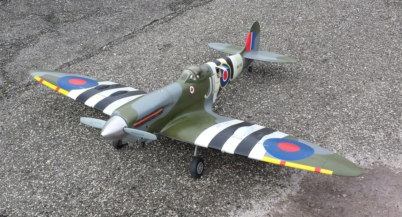
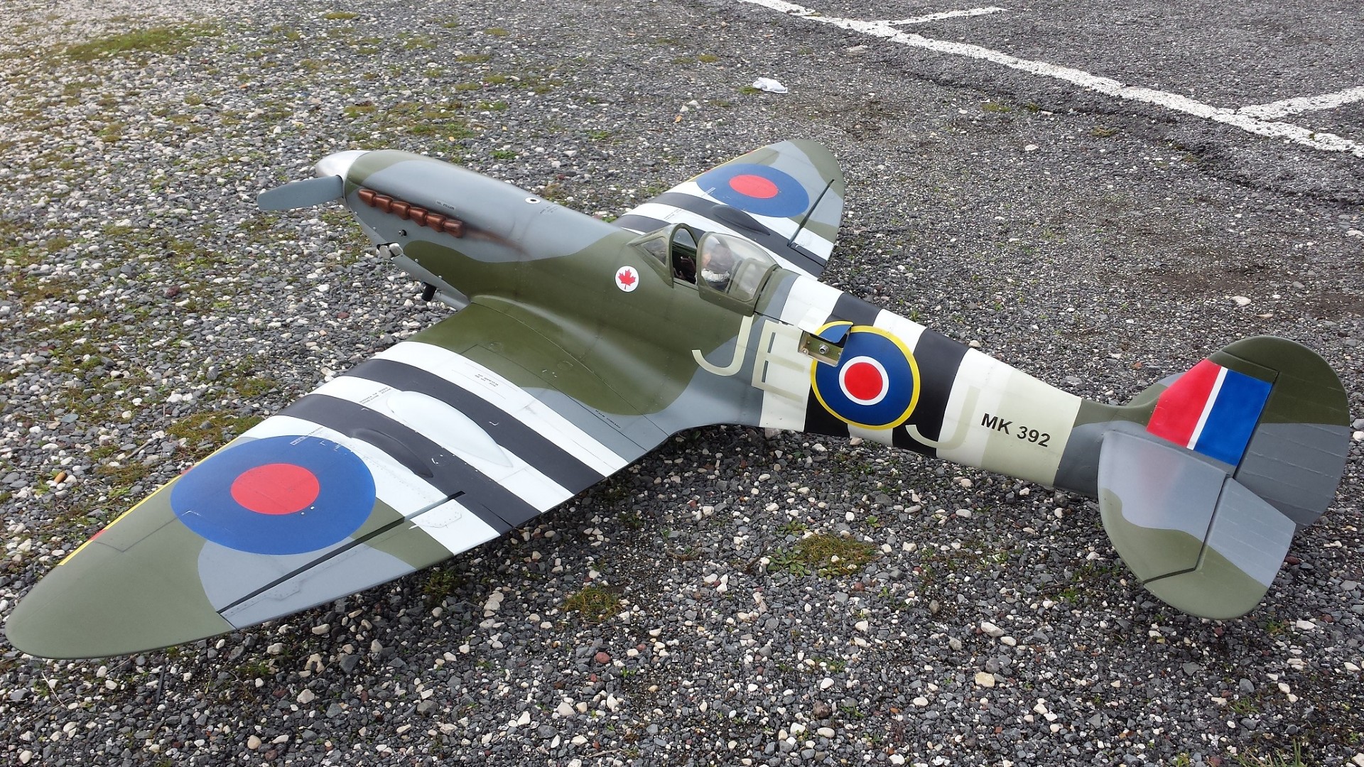
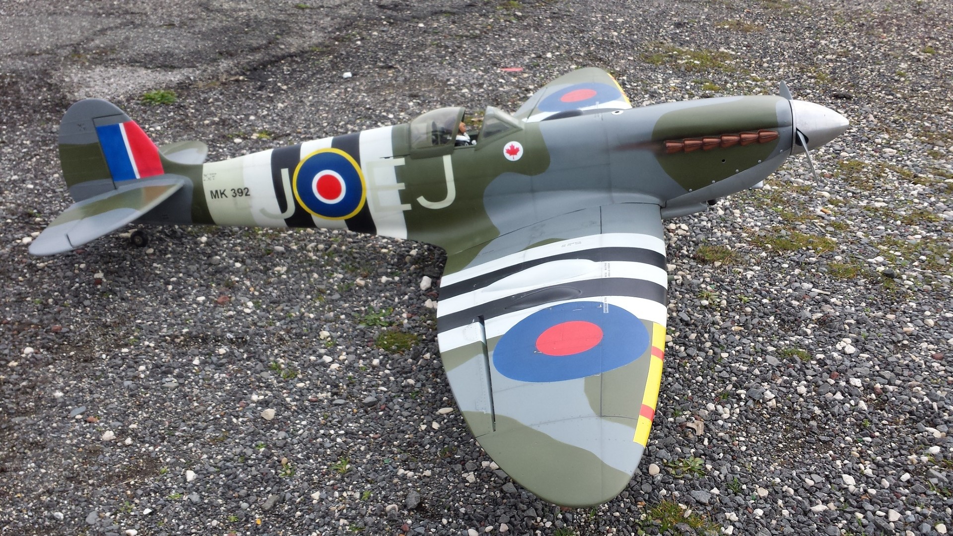
Images Source: RC Universe Webpage.
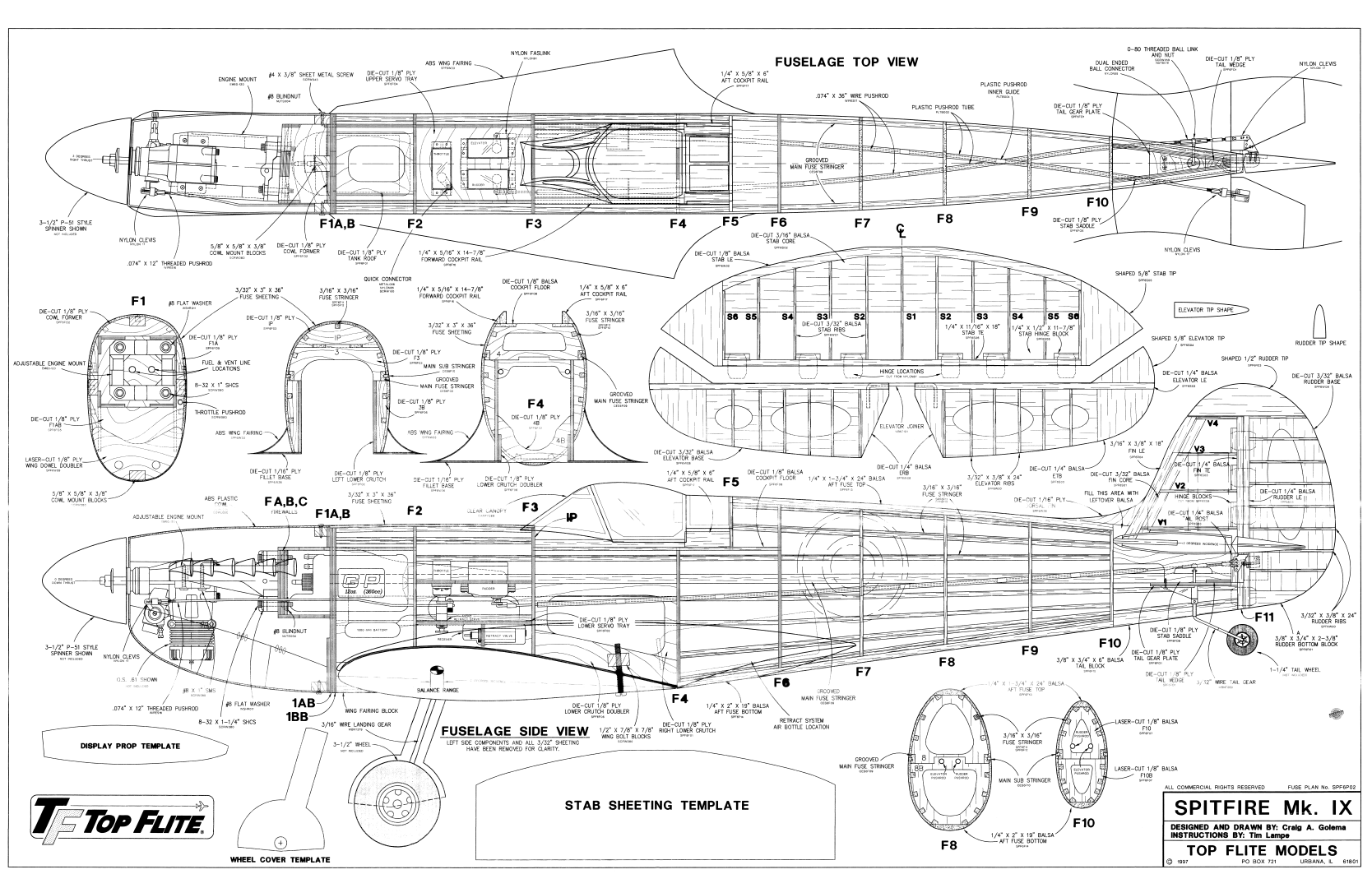
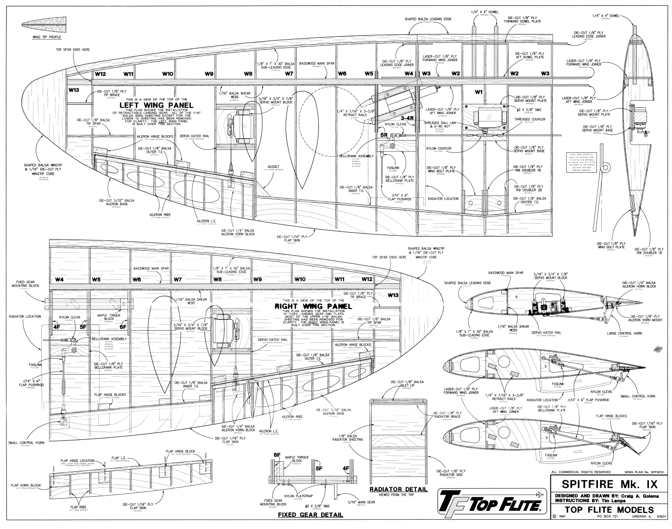
Plan Images are extracts from Top Flite Plans.
RC MODEL CONSTRUCTION: The Top Flite Gold Edition Spitfire model was chosen to replicate the Mk IX — the second most popular Spitfire ever, reaching a total production of 5,665 aircraft. Considered to be the finest Spitfire of all, the Mk IX went into operational service in July, 1942. The RC model was designed and plans drawn by Craig A. Golema, and the instructions are by Tim Lampe.
Craig's plans are full-size, clearly laid out, and give part locations and descriptions. The plans are used in conjunction with a well-illustrated assembly manual into which Tim has obviously put a lot of work into. Included are not only pictures and step-by-step text, but helpful building tips to make the job easier. Everything you need to know is in it. Just to name a few other items needed to complete the model like hardware, building supplies, tools, and a layout of the die-cut parts. Then there are also sections on engine types, retracts, flaps, and even some tips on scale detailing! What more could you ask for!
Recommended engine sizes include .61-.75 cu. in. 2-stroke, or .70-.91 cu. in. 4-stroke. The Spitfire will fly well with any of the recommended engines. The 4-stroke engines and most .75 cu. in. 2-stroke engines will turn a larger prop at lower RPM. This is often desirable for scale realism. Many .61 cu. in. 2-stroke engines produce about as much horsepower as the popular .75 2-stroke engines and will fly the Spitfire extremely well. If you use a .61 2-stroke, a ball bearing, Schnuerle-ported engine is recommended. The prototype Spitfire weighs 9-1/2 pounds with all of the options, including flaps and the scale cockpit interior and was flown with an O.S. .61 cu. in. engine. This engine provided excellent performance and more than enough power. Although larger engines can be used to power this model, the extra horsepower is not needed.
You can build your Spitfire either with fixed or retractable landing gear. Of course, fixed landing gear will be easier to install than retracts; but Top Flite provides detailed instructions on retract installation so you should have no trouble. The Gold Edition Spitfire is designed to accept the Robart #605 90 degree HD (Heavy Duty with 3/16" struts) pneumatic retracts. You may use other retractable landing gear systems but it is up to you to make any modifications that may be necessary. The Spitfire's fuselage is large enough for straight forward radio gear installation and it still allows plenty of room for the optional scale cockpit kit and retract air tank.
The Top Flite Spitfire is designed to incorporate scale split flaps; however, flaps are optional and not necessary for an excellent flying experience. Without flaps, the takeoff roll is longer and the landing speed is faster. The flaps are not difficult to build, but they do require good craftsmanship to fit well. Flaps add nicely to the model's flight characteristics and scale appearance. Only slight trim correction is needed when flaps are used with the recommended throws. Flaps are highly recommended for those who wish to install them.
- RC Model Specifications:
- Aircraft Type: 1/7th Sport Scale Warbird
- Wing Span: 63″
- Total Wing Area: 687 square inches
- Wing loading: 25-28.5 oz/sq. in.
- Wing Location: Low Wing
- Wing Platform: Double Taper
- Fuselage Length: 53″
- Center of Gravity: 4-1/8″ from the leading edge of the wing
- Number of Channels: 4-6 - Throttle, Ailerons, Rudder, Elevator, Flaps, and Retract Gear
- Ready to Fly Weight: 7.5-8.5 lbs. depending on power system selection
- Glow Fuel Engines: .61-.75 cu. in. 2-stroke, or .70-.91 cu. in. 4-stroke
- Electric Powered: Output of 1,200-1,500 Watts, 80 Amp ESC, 6 cell 45C LiPo pack of 5,000mah, and APC 11x7 - 14x7 E-series prop.
The Spitfire Mk IX RC model in this months edition can be built using a set of full-size plans, assembly manual, and review article available @: “Outerzone.”
Outerzone Spitfire Mk IX Webpage.
I hope you have enjoyed this months selection, and just maybe, I have spurred some interest in trying your hand at building an RC model airplane.
Until next month - Keep the Balsa Dust Flying!!
Build of the Month WW-II Mini-Series - January 2025 Edition
I hope you enjoyed last months BOTM WW-II Mini-Series 3rd Edition on the Mitsubishi A6M Zero model. If you have an RC model that you would like to see featured in this section or feel others may find interesting, please let me know and I will make every attempt to find scratch build plans, photos, and maybe even a published build article, which will then post in a future edition. Just send me an email @: Build of the Month.
Ok, now lets see what I have for the month of January 2025. Continuing with the “BOTM WW-II Mini-Series,” for the 4th Edition we will move back to the European Theater and this time on the Eastern Front. How about a fighter that was the single most produced military aircraft design in aviation history. So given these requirements, this 4th Edition of my BOTM WW-II Mini-Series features the Ilyushin IL-2 Stormovik, a fighter manufactured by the Soviet Union.
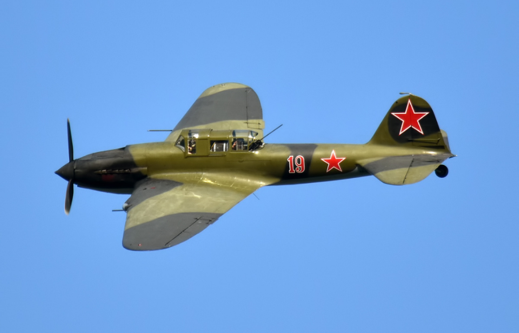
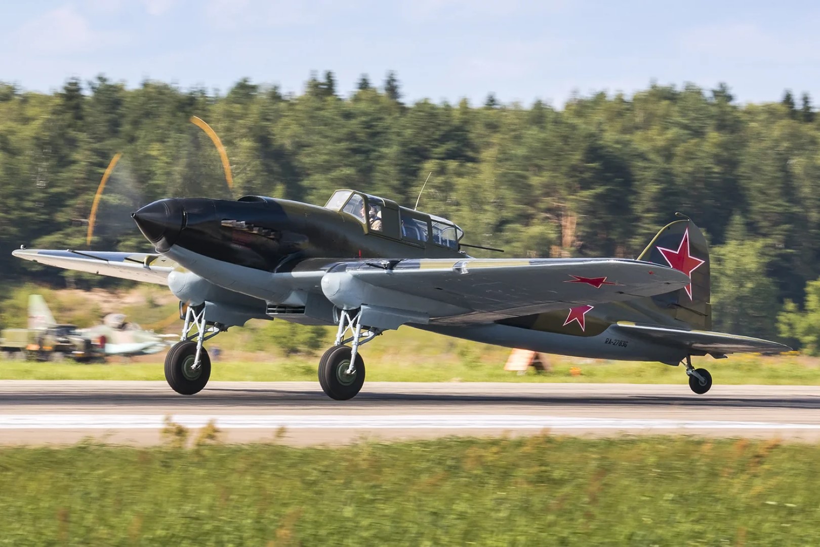
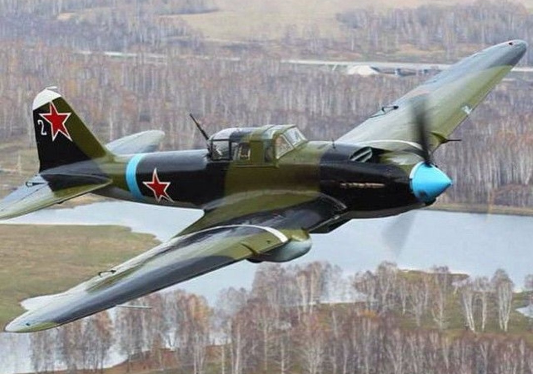
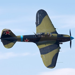
The Ilyushin IL-2 is a ground-attack plane that was produced by the Soviet Union in large numbers during the Second World War. To IL-2 pilots, the aircraft was known by the diminutive "Ilyusha". To the soldiers on the ground, it was called the "Hunchback", the "Flying Tank" or the "Flying Infantryman". Its postwar NATO reporting name was Bark.
The IL-2 was designed by Sergey Ilyushin and his team at the Central Design Bureau in 1938. During the war, 36,183 units of the IL-2 were produced, and in combination with its successor, the Ilyushin IL-10, a total of 42,330 were built, making it the single most produced military aircraft design in aviation history, as well as one of the most produced piloted aircraft in history along with the American postwar civilian Cessna 172 and the German then-contemporary Messerschmitt Bf-109.
The IL-2 played a crucial role on the Eastern Front. When factories fell behind on deliveries, Joseph Stalin told the factory managers that the IL-2s were "as essential to the Red Army as air and bread."
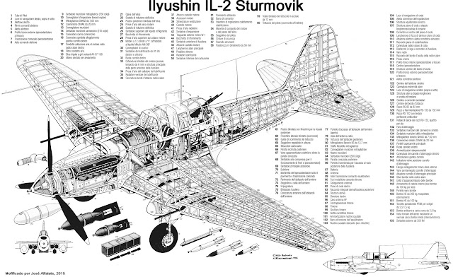
The IL-2 was anything but advanced in its mixed wood-and-metal construction, which was relatively easy to manufacture in significant numbers using relatively unskilled workers. But for an aircraft, it was an amazing achievement. Among the Shturmovik’s most important assets were its strength and robustness in combat. The forward fuselage section, protecting the aircraft’s fuel system, radiators and crew station, was built entirely of armor plate. Thus, the IL-2 could, and often did, absorb extraordinary battle damage and survive to fight another day. The protective armor shell employed a special alloy developed for the IL-2; its thickness varied by location on the airframe. Special consideration had been given to a technology that would allow maintenance personnel to stamp the armor steel in the field, thus providing flexibility in the design, especially when Soviet units were forced to operate from primitive forward battle areas.
The IL-2 continued in service into the Cold War period (1947-1991) where it was delivered to Soviet allies across Europe. Bulgaria took on a fleet of 120 IL-2 attackers and 10 IL-2U trainers in 1934 and operated these well into 1954. Similarly, the IL-2 formed a portion of the Hungarian Air Force, and these were flown into 1952. Czechoslovakia took on 33 IL-2 attackers and 2 trainer forms for their part and operated them during the war in 1944 into 1949. Mongolian Army Aviation fielded 71 IL-2 aircraft from 1945 onwards and actively supported them into 1954. Yugoslavia fielded the IL-2 in no fewer than ten Air Force squadrons - the last ones were retired in 1954.
The legacy of the IL-2 lives on today in the Sukhoi Su-25 "Frogfoot", the Soviet answer to the American Fairchild Republic A-10 "Thunderbolt II" (Warthog). Like the IL-2, the Su-25 bristles with a broad armament array (missiles, rockets, gunpods and the like), is developed for low-altitude fighting, and has survivability features such as an ejection seat, twin-engine configuration, and armored systems and sub-systems not to mention active and passive warning and countermeasures systems.
- Actual Aircraft Specifications:
- Crew: Two
- Length: 11.65 m (38 ft 3 in)
- Wingspan: 14.60 m (47 ft 11 in)
- Height: 4.17 m (13 ft 8 in) (tail up)
- Wing area: 38.50 m2 (414.4 sq ft)
- Empty weight: 4,425 kg (9,755 lb)
- Max takeoff weight: 6,360 kg (14,021 lb)
- Power plant: 1 – Mikulin AM-38F liquid-cooled V12 engine, 1,280 kW (1,720 hp) (takeoff power), 1,100 kW (1,500 hp) at 750 m (2,460 ft)
- Propellers: 3-bladed AV-57-158 variable-pitch propeller, 3.60 m (11 ft 10 in) diameter
- Maximum speed: 410 km/h (250 mph, 220 kn) at 1,500 m (4,900 ft)
- Range: 765 km (475 mi, 413 nmi) at 275 km/h (171 mph; 148 kn) and 1,000 m (3,300 ft)
- Service ceiling: 4,525 m (14,846 ft) (service ceiling), 6,360 m (20,870 ft) (absolute ceiling)
- Guns: 2 – fixed forward-firing VYa-23 cannons, 150 rounds per gun
- 2 – fixed forward-firing ShKAS machine guns, 750 rounds per gun
- 1 – manually aimed Berezin UBT machine gun in rear cockpit, 300 rounds
- Rockets: 8 – RS-82 rockets or 4 – RS-132 rockets
- Bombs: 6 – 100 kg (220 lb) bombs in wing bomb-bays and underwing, or 4 – dispensers for 48 – 2.5 kg (5.5 lb) PTAB anti-armour bombs (192 total) in wing bays
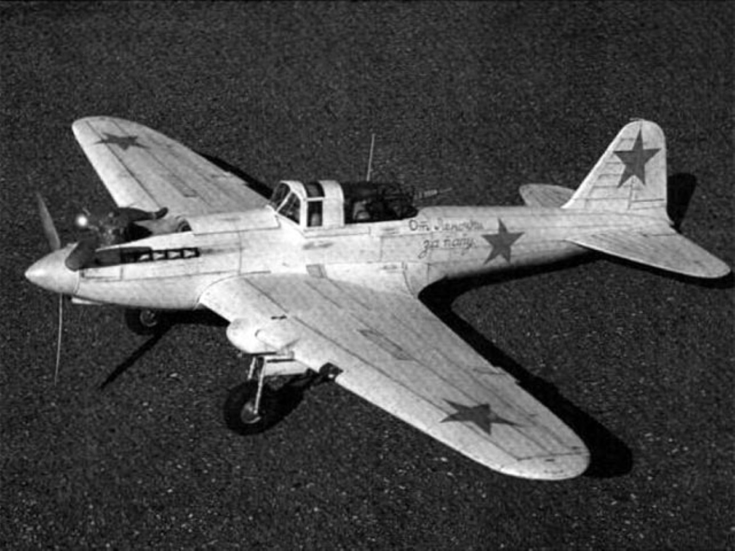
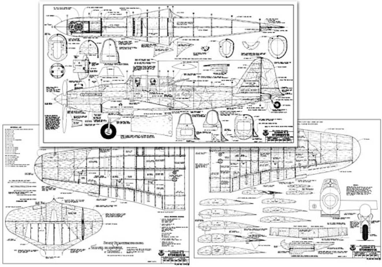

Source of Images: Outerzone Ilyushin IL-2 Stormovik Webpage.
RC MODEL CONSTRUCTION: The Stormovik was as important to Russia as the Spitfire was to Great Britain and the Mustang was to America, yet the Stormovik is not well known in the West. Perhaps we modelers can do something about that. As a scale model, the Stormovik has excellent moments. It has a high-lift airfoil, a long, slender fuselage, a huge tail, and short, wide-apart landing gear with big wheels. The full-size Stormovik was designed for rough-field operation and low-speed stability - just the qualities we seek in a scale subject.
It's odd that it is rarely seen in model form; the only other RC design I know of is Bob Underwood's version which placed in the AMA Nats in the early 80s. The Stormovik presented here was prepared by photo-enlarging the Aeromodeler/MAP drawings and filling in the structure. It is exact; no deviations from scale were permitted. If you use the Aeromodeler drawings for “proof of scale” documentation and you follow the plans faithfully, you should receive a perfect score for “accuracy of outline” in AMA scale contests. Only part of the Aeromodeler drawing is presented here; the complete drawing contains additional views and more detail. The Profile publication number 88 is apparently derived from the same Aeromodeler drawing, so it is also excellent scale documentation plus it contains many color schemes.
Upgrading to Precision Scale or FAI scale is possible by adding more details. If you decide to build this airplane, you should first gather all scale documentation before cutting the first piece of wood (see the list of references on the plans). Then, wait for a cold Siberian night, put on your boots and babushka, and march down to your shop. Shove a tape of Shostikovitch's Leningrad Symphony into the stereo and toast a “salut” to Mother Russia. Let's begin..."
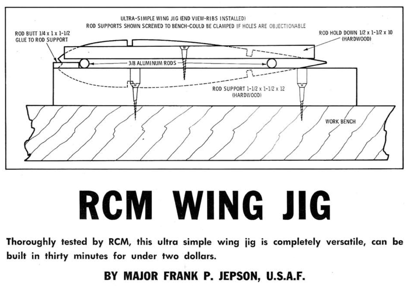
WING: Wing construction starts with making wing ribs. It is important to drill the 1/4″ wing rod holes as accurately as possible. Don't drill these holes with a twist drill, it will tear balsa wood instead of cutting it, and it does not permit accurately centering the drill. Here is a better way to do it. Cut a 3/4″ section of 1/4″ O.D. brass tube. Bevel the inside edge of one end with a Dremel grinding stone. Grind the edge to be as sharp as possible. Chuck this in your drill press or electric hand drill. Place a wing rib on a flat piece of pine and slip it under the drill press. Lower the brass tube, motor off, until the tube touches the 1/4″ circle marked on the rib. Align to a perfect match and turn on the drill. Lower the tube slowly until resistance is felt and withdraw. Voila! - a perfect hole. Remove the tube and push out the balsa plug. Resharpen after every 10 holes.
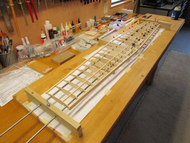
The wing is built on a wing jig, one panel at a time. If you have a commercial wing jig, use it. Otherwise, buy two 3′, 1/4″ steel rods from the local hardware store. Apply a very thin coat of oil to the rods, just in case some glue spills on them. Lay these over the wing plan, raised on short sections of wooden blocks beyond the root rib and tip rib. The image below shows my wing jig being used to build a Bokkie wing. It works GREAT! You can build the same wing jig using the August 1967 RCM Article available @: RCBookcase.com.
FUSELAGE: The fuselage structure is “flat sides and formers” typical of pattern ships and non-scale airplanes. Use light materials for everything aft of the Center of Gravity and hollow the tail blocks to save weight. Use only 4-6 pound grade balsa. Remember that any unnecessary weight in the tail must be paid for by 6 times as much counterweight in the nose, and all unnecessary weight degrades performance.
FLIGHT CHARACTERISTICS: Check and double-check the balance point (C.G.) as shown on the plans. Further forward is okay, but don't let the C.G. be aft of this point. If the plane turns out to be considerably heavier than 9 pounds, the C.G. should be even further forward. Ground handling is outstanding. No up elevator is required for starting the take-off roll, just hit the loud-lever and steer with the rudder. When properly trimmed, it will lift off by itself. Good ground handling is to be expected, considering the rough field conditions for which the original was designed.
The plane is quite stable and very smooth flying. Slow rolls are axial and uniform in roll rate. Low passes are chilling, this is the airplane that destroyed 70 German tanks in 20 minutes. When you see those cannon barrels coming at you and you hear the engine snarling, remember that the German Army called this airplane Schwarz Tod — “Black Death.” The flaps are very effective. Steep descents for landing with full flap cause no buildup in airspeed. 40 degrees of flap is about right for a normal landing approach or for slow fly-bys. This permits slow flight without loss of stability. But full flap should be used only in steep descents, they slow the airplane too much in level flight. The stronger the wind, the less flap deflection. If the wind is greater than 15 mph, don't use any flap at all for landings. Never use flaps for take-offs except, perhaps, partial flap in dead-calm air.
Spins are slow with no tendency to become flat. Neutralizing the rudder and elevator instantly stops the spin. At the elevator throw shown on the plans, entry to the spin is critical. If you wish to do spins as a contest maneuver, you must use greater elevator throw for more reliable spin entrance, a good application for dual rates.
- RC Model Specifications:
- Aircraft Type: Sport Scale Warbird
- Wing Span: 70″
- Wing Chord: 18″ Root, 7″ Tip
- Total Wing Area: 880 square inches
- Wing Location: Low Wing
- Airfoil: 14 percent Scale Flat Bottom
- Wing Platform: Double Taper
- Dihedral each Tip: 2″
- Fuselage Length: 58″
- Stabilizer Span: 25″
- Stabilizer Chord (including elevator): 9″
- Total Stab Area: 235″
- Number of Channels: 6 - Throttle, Ailerons, Rudder, Elevator, Flaps, and Retract Gear
- Ready to Fly Weight: 144 oz. depending on power system selection
- Glow Fuel Engines: .90 - 1.08 2-stroke or 1.2 4-stroke
- Electric Powered: Output of 1,800-2,400 Watts, 80-120 amp ESC, 4-6 cell 45C LiPo pack of 5,000mah.
The Ilyushin IL-2 Stormovik RC model in this months edition can be built using a set of plans and article which are available @: “Outerzone.”
Outerzone Ilyushin IL-2 Stormovik Webpage.
I hope you have enjoyed this months selection, and just maybe, I have spurred some interest in trying your hand at building an RC model airplane.
Until next month - Keep the Balsa Dust Flying!!
Build of the Month WW-II Mini-Series - December 2024 Edition
I hope you enjoyed last months BOTM WW-II Mini-Series 2nd Edition on the Bell P-39 Airacobra model. If you have an RC model that you would like to see featured in this section or feel others may find interesting, please let me know and I will make every attempt to find scratch build plans, photos, and maybe even a published build article, which will then post in a future edition. Just send me an email @: Build of the Month.
Ok, now lets see what I have for the month of December 2024. Continuing with the “BOTM WW-II Mini-Series,” for the 3rd Edition we will move from the European Theater to the Pacific Theater. How about a fighter that was instrumental in bringing the United States into WW-II. So given these requirements, this 3rd Edition of my BOTM WW-II Mini-Series features the Mitsubishi A6M Zero, a fighter manufactured by Mitsubishi Aircraft Company.
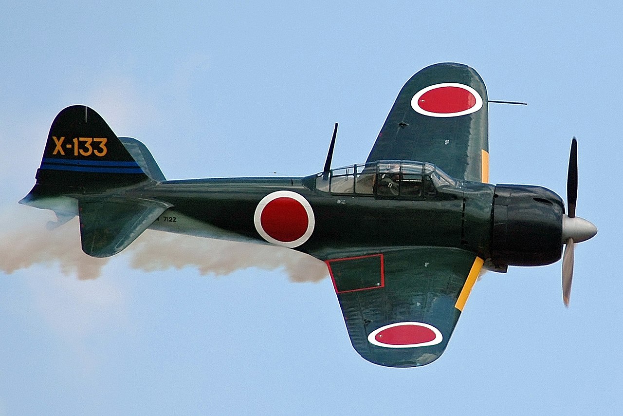
The Mitsubishi A6M Zero might have played a more significant role than any other fighter in a single sortie during WW-II. This snub-nosed compact carrier-based plane was named the “Zero” after year zero in honor of Japan's first emperor's ascension to power 2,600 years before its launch. This outlines the long Japanese tradition as a nation skilled in combat and weaponry.
The Zero was incredibly nimble, well-equipped, and lightweight, with its designer Jiro Horikoshi using aluminum and plywood instead of steel as a weight-saving measure. A zinc-aluminum alloy was specially concocted for more stressed components, making this a meticulously designed plane, delivered in a timely manner by 1940, having gone into production in 1937. Its 14-cylinder 1,130 horsepower engine propelled it to a top speed of 350 miles per hour, and its armament consisted of two 7.7-millimeter machine guns and two 20-millimeter cannons, with its two notorious 132-pound bombs beneath each wing.
The Mitsubishi Zero will forever be remembered as the plane that was instrumental in bringing the United States into WW-II. On December 7th, 1941, under the attack signal, “Tora! Tora! Tora!” the Japanese launched their assault on Pearl Harbor, with the fleet of Zeros raining mayhem from above, strafing the docks with gunfire and devastating the U.S. Navy fleet with bombs. They quickly gained a reputation among the deadliest aircraft as the United States immediately declared war on Japan. Just three days later, the U.S. was also at war with Germany.
Also called “Reisen” or “Zeke”, the Mitsubishi A6M Zero served as a nasty shock to the Allied Forces. Being the primary naval fighter of the Imperial Japanese Navy, it was a legendary dogfighter with very long range and incredible maneuverability. It boasted of speed and impressive endurance. It was a formidable fighter with a kill ratio of 12 to 1. In the Pacific Theater, it could easily best its ground-based counterparts thus swiftly earning a legendary reputation. During WW-II, it became the Japanese aircraft with the most number built and produced. It wasn't just a symbol of their air superiority and power, it also paved the way for numerous innovations in naval aviation. Faced against the Grumman F4F Wildcat, Brewster F2A Buffalo, and the Curtiss P-40, it could out-maneuver them all. Yes, it was indeed a tough opponent – a very lethal fighter in dogfight. It also took part in various devastating attacks against the Allied forces.
Toward the end of the Pacific War, the large numbers of Zero fighters in service and their high maneuverability made them ideal for suicide special attacks, more popularly known to westerners of the day as “kamikaze”. Out of the 2,363 Japanese Navy aircraft that participated in special attack missions, 1,189 of them were A6M Zero fighters.
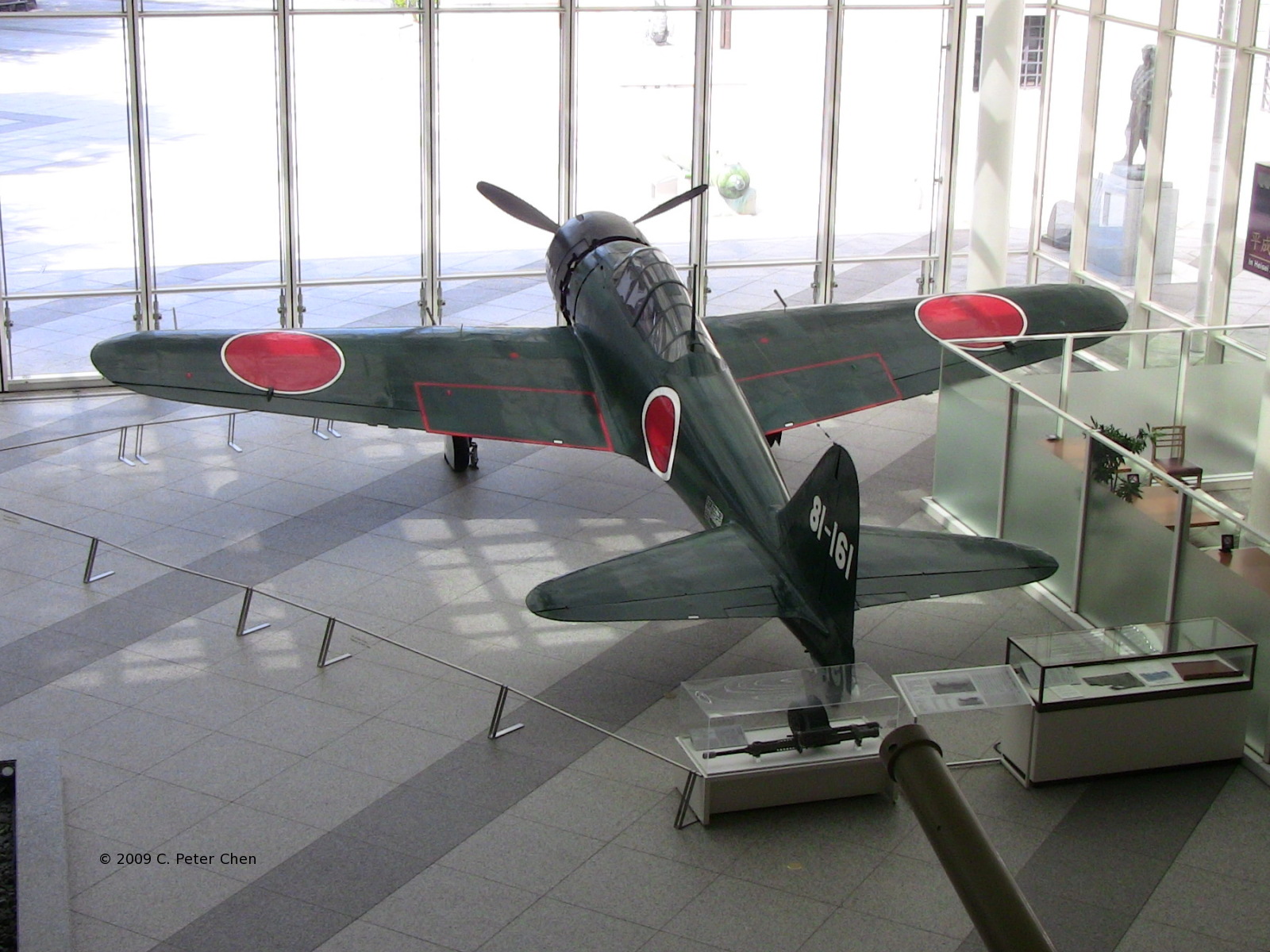
After the war, most surviving A6M Zero fighters were destroyed. A few of them were sent to the United States for testing. Many of them were abandoned across the various Pacific islands, rusting very quickly in jungle climates. Only about 13 were available for museum display today, such as the Zero fighter on display at Yushukan museum adjacent to the Yasukuni Shrine in Tokyo, Japan. Only a very small number are in flyable condition today.
- Actual Aircraft Specifications (A6M2 (Type 0 Model 21)):
- Crew: One
- Length: 9.06 m (29 ft 9 in)
- Wingspan: 12 m (39 ft 4 in)
- Height: 3.05 m (10 ft 0 in)
- Wing area: 22.44 m2 (241.5 sq ft)
- Empty weight: 1,680 kg (3,704 lb)
- Gross weight: 2,796 kg (6,164 lb)
- Max takeoff weight: 2,796 kg (6,164 lb)
- Power plant: 1 – Nakajima NK1C Sakae-12 14-cylinder air-cooled radial piston engine, 700 kW (940 hp) for take-off 710 kW (950 hp) at 4,200 m (13,800 ft)
- Propellers: 3-bladed Sumitomo-Hamilton constant-speed propeller
- Maximum speed: 533 km/h (331 mph, 288 kn) at 4,550 m (14,930 ft)
- Cruise speed: 333 km/h (207 mph, 180 kn)
- Never exceed speed: 600 km/h (370 mph, 320 kn)
- Range: 1,870 km (1,160 mi, 1,010 nmi)
- Service ceiling: 10,000 m (33,000 ft)
- Rate of climb: 15.7 m/s (3,090 ft/min)
- Guns: 2 – 7.7 mm (0.303 in) Type 97 aircraft machine guns in the engine cowling, with 500 rounds per gun
- 2 – 20 mm (0.787 in) Type 99-1 Mk.3 cannon in the wings, with 60 rounds per gun
- Bombs: 2 – 60 kg (130 lb) bombs or 1 – fixed 250 kg (550 lb) bomb for kamikaze attacks
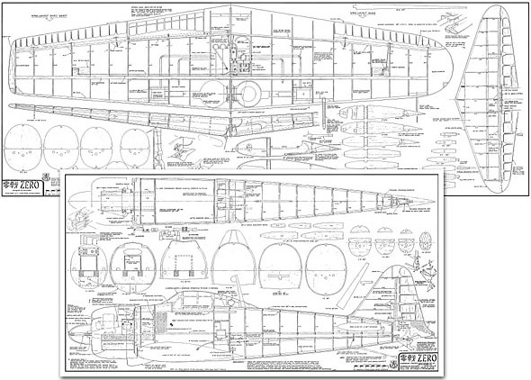
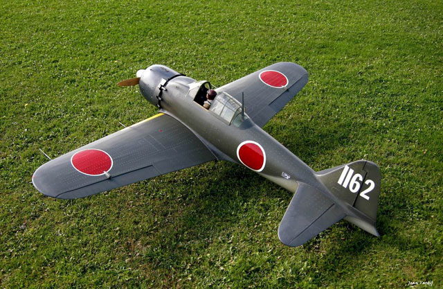
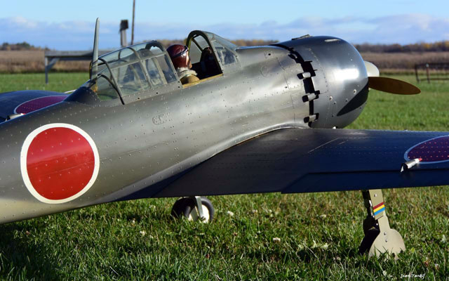
Images Source: Outerzone Mitsubishi A6M Zero Webpage.
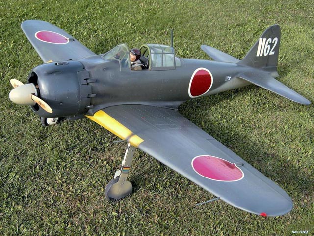
RC MODEL CONSTRUCTION: The model featured this month was designed by Dave Platt and featured in Radio Control Modeler (RCM) Magazine May 1984. As we shall see, it turns out that just about all of the assets that the Zero possesses to make it a fine R/C model are the same inherent requirements that were demanded by the specification laid before the designers of the full sized ship. Before all else, it had to be light. This was to make sure it would be totally maneuverable and aerobatic; primary requisites for a dogfighter. These needs dictated a simple structure (and thus a straightforward outline), a large wing area coupled with a thick airfoil, and large control surfaces. In this last respect, the Zero's ailerons are perfect for a model: narrow chord (avoiding tip-stalls from high deflection angles at the tip) but long in span, giving them a lot of area.
The ideal layout for power with gentleness.
In just one respect the Zero comes up short; literally short. The nose moment is not as long as we would choose. The danger here is coming up with a rather tail heavy airplane needing much nose weight to correct. And, by extension, an overall heavy model. When Platt was laying out his Zero, he decided to design all structure aft of the wing spar as lightly as possible; not merely the tail end. Conversely, the nose end was designed like a tank. It worked. The original prototype, with O.S. Max .90, weighed 14-1/2 lbs. and balanced right without nose weight. Scratch builders will need to keep weight in mind; not how much there is, but where it is.
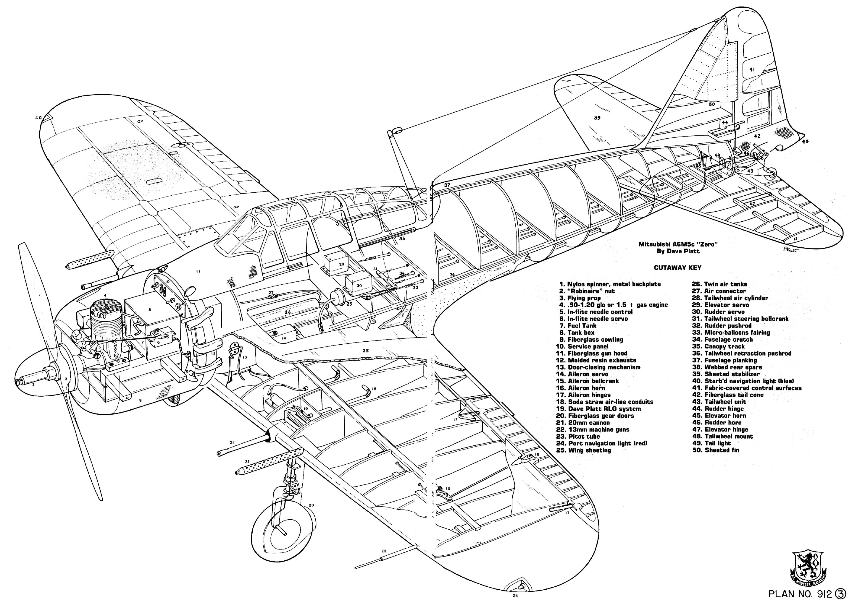
BUILDING: This section is not intended to be a step by step procedure for building but, rather, a brush across some of the highlights of the structural design. Certain parts were deemed necessary to make in fiberglass: the cowling, obviously; the gun hood because of its complex and subtle shaping; and the tail cone which again is a complicated shape and also needs to be hollow. The model is of conventional wood design. The fuselage can be skinned with large panels, or can be strip-planked. The latter method, though taking longer, produces a better, stronger result. In fact, with the CA glues we now use, the time taken to plank a body properly is little more than skinning, and only a fraction of what it used to be “pre-Zap.”
The plans show the flaps, which can be installed if desired or left off. While the cosmetic effect achieved by including them is undeniable, their functional usefulness in slowing down the ship in landing approaches becomes somewhat moot, since the unwavering stability during approach and slow landing speed could scarcely be improved. The plans also include details of the square tipped “Hamp,” or A6M3. Apart from the square tips, if you choose the -3, the cowl gills are not cut away and the multi-exhaust stubs are left off. The addition of a streamlined fairing around the drop tank attachment, and different gun arrangement complete the conversion.
The cutaway drawing shows the basic simplicity of structure. The Zero is a simple aircraft, and there was no call for sophisticated or complex design. Note that the entire cockpit bay area is left free of unwanted structure or radio components. This enables the builder to fit the available cockpit kit in place and have it look right. Along with the available Japanese feature pilot, an attractive cockpit area is achieved without special skills or experience.
Whether for serious competition or relaxed fun, this is a flying machine par excellence. Credit for this, as explained, lies with the Mitsubishi design team. The only maneuver the Zero won't do well is a knife-edge. This could be due to the somewhat excessive dihedral. But all the rest, look out! Rolls --- regular, slow, four-point or vertical --- a snap. Loops, Cuban Eights, touch 'n go's. Lovely solid inverted. Spins, no problem, recovery in 1/4 turn. Inverted spins too. When did you see one of these from a true scale model WW-II fighter? Come to that, when did a WW-II fighter ever do one intentionally?
- Model Specifications:
- Aircraft Type: 1/5th Scale Warbird
- Wing Span: 78-3/4″
- Wing Chord: 14-1/2″ (Avg.)
- Total Wing Area: 1,100 square inches
- Wing Location: Low Wing
- Airfoil: Semi-Symmetrical
- Wing Platform: Double Taper
- Dihedral each Tip: 4-5/8″ at W11
- Fuselage Length: 65″
- Stabilizer Span: 33″
- Stabilizer Chord (Avg.): 8-1/4″
- Total Stab Area: 255″
- Number of Channels: 8 - Throttle, Ailerons, Rudder, Elevator, Flaps, Retract Gear, Tank Drop, and Mixture Control
- Ready to Fly Weight: 232-320 oz. depending on power system selection
- Glow Fuel Engines: .90 - 1.5 2-stroke or 1.8 cu. in. Gas
- Electric Powered: Output of 1,800-3,000 Watts, 80-125 amp ESC, 4-6 cell 45C LiPo pack of 5,000mah.
The Mitsubishi A6M Zero RC model in this months edition can be built from a set of plans and article which are available @: “Outerzone”
Outerzone Mitsubishi A6M Zero Webpage.
I hope you have enjoyed this months selection, and just maybe, I have spurred some interest in trying your hand at building an RC model airplane.
Until next month - Keep the Balsa Dust Flying!!
Build of the Month WW-II Mini-Series - November 2024 Edition
I hope you enjoyed last months BOTM WW-II Mini-Series 1st Edition on the Junkers Ju-52/3m model. If you have an RC model that you would like to see featured in this section or feel others may find interesting, please let me know and I will make every attempt to find scratch build plans, photos, and maybe even a published build article, which will then post in a future edition. Just send me an email @: Build of the Month.
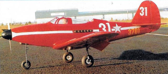
Ok, now lets see what I have for the month of November 2024. Continuing with the “BOTM WW-II Mini-Series,” for the 2nd edition how about an aircraft that was used by several nations during the war and has an unusual layout with the engine installed in the center fuselage, behind the pilot. So given these requirements, this 2nd edition of my BOTM WW-II Mini-Series features the Bell P-39 Airacobra, a fighter produced by Bell Aircraft for the United States Army Air Forces during WW-II.
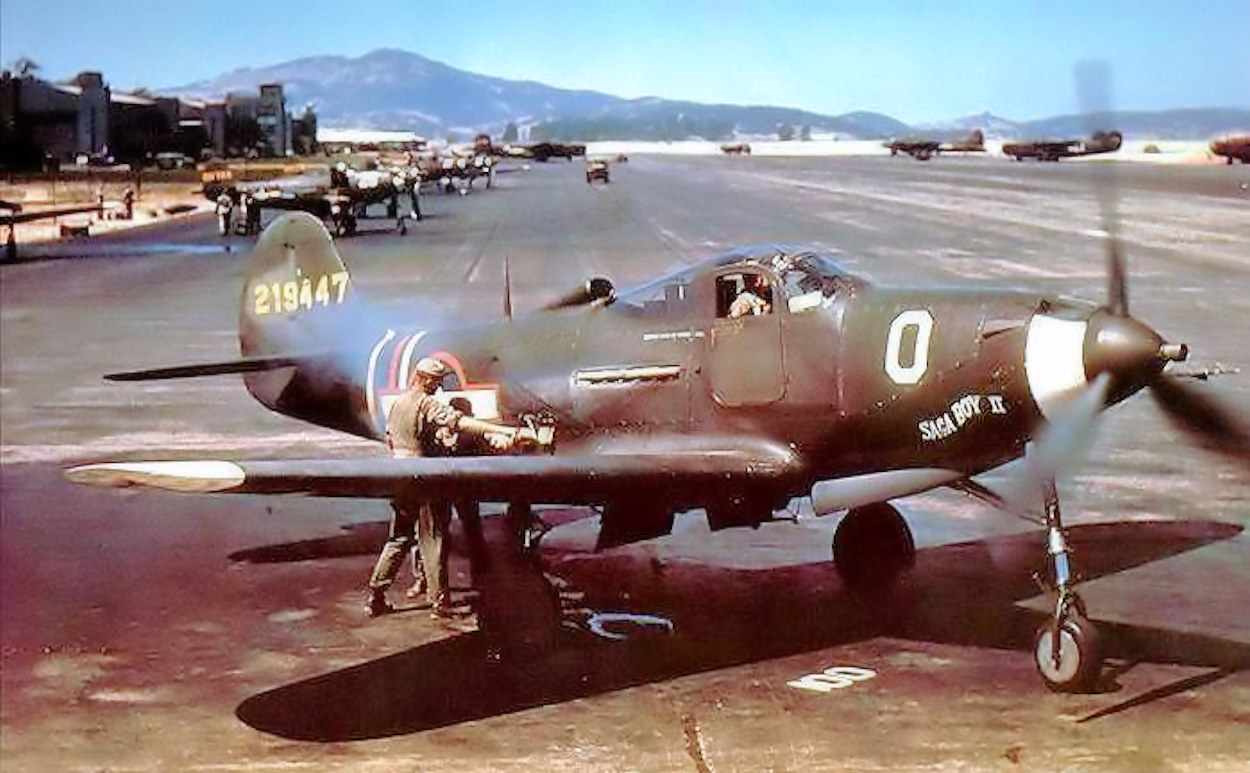
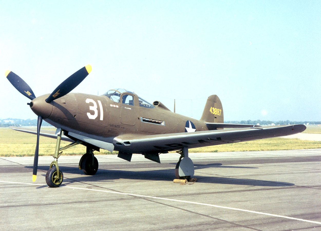
The Bell P-39 Airacobra is a fighter produced by Bell Aircraft for the United States Army Air Forces during WW-II. It was one of the principal American fighters in service when the United States entered combat. The P-39 was used by the Soviet Air Force and enabled individual Soviet pilots to score the highest number of kills attributed to any U.S. fighter type flown by any air force in any conflict. Approximately 9,560 Airacobras were produced, about half of which were sent to Russia under the Lend-Lease program. Production models of the P-39 started arriving at Air Corps squadrons in January 1941; six months later the first Airacobras reached England. The British had planned to order 675 of the planes, but after disappointing combat experience, the order was canceled. Other major users of the type included the Free French, the Royal Air Force (RAF), and the Italian Co-Belligerent Air Force.
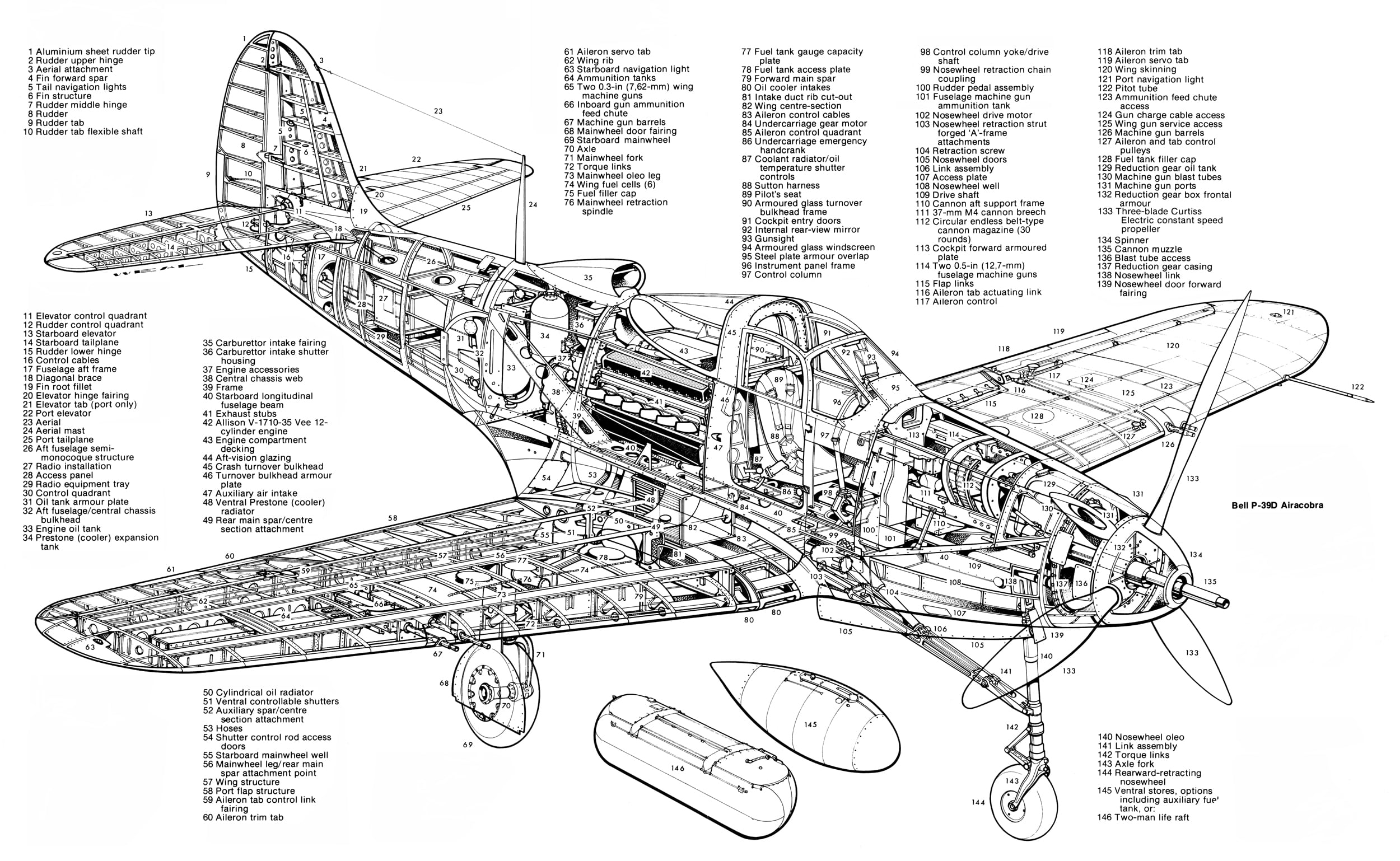
The Bell engineers wanted to mount the cannon so it would fire directly through the propeller shaft. This meant the engine would have to be located deep in the fuselage. This, in turn dictated that the machine would have a tricycle gear undercarriage -- the first such ever used on a production fighter. It had an unusual layout, with the engine installed in the center fuselage, behind the pilot, and driving a tractor propeller in the nose with a long shaft. Although its mid-engine placement was innovative, the P-39 design was handicapped by the absence of an efficient turbo-supercharger, preventing it from performing high-altitude work. For this reason, it was rejected by the RAF for use over western Europe but adopted by the USSR, where most air combat took place at medium and lower altitudes.
Together with the derivative P-63 Kingcobra, the P-39 was one of the most successful fixed-wing aircraft manufactured by Bell.
- Actual Aircraft Specifications (Bell P-39 Airacobra):
- Crew: One
- Length: 30 ft 2 in (9.19 m)
- Wingspan: 34 ft (10.36 m)
- Height: 12 ft 5 in (3.78 m)
- Wing area: 213 sq ft (19.8 m2)
- Empty weight: 6,516 lb (2,956 kg)
- Gross weight: 7,570 lb (3,434 kg)
- Max takeoff weight: 8,400 lb (3,810 kg)
- Power plant: 1 – Allison V-1710-85 V-12 liquid-cooled piston engine, 1,200 hp (890 kW) at 9,000 ft (2,743 m) (emergency power)
- Propellers: 3-bladed constant-speed propeller
- Maximum speed: 389 mph (626 km/h, 338 kn)
- Stall speed: 95 mph (153 km/h, 83 kn) power off, flaps and undercarriage down
- Never exceed speed: 525 mph (845 km/h, 456 kn)
- Range: 525 mi (845 km, 456 nmi) on internal fuel
- Service ceiling: 35,000 ft (11,000 m)
- Rate of climb: 3,805 ft/min (19.33 m/s) at 7,400 ft (2,300 m) (using emergency power)
- Guns: 1 – 37 mm M4 cannon firing through the propeller hub
- 2 – .50 caliber synchronized Browning M2 machine guns, nose-mounted
- 2 – .50 caliber Browning M2 machine guns one each wing
- Bombs: Up to 500 lb (230 kg) of bombs under wings and belly
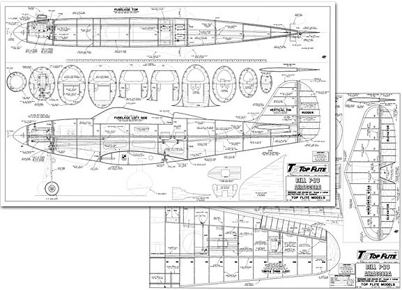
Images Source: Outerzone Bell P-39 Airacobra Webpage.
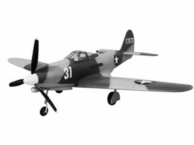
RC MODEL CONSTRUCTION: The model featured this month is a discontinued Gold Edition kit from Top Flite. The nice thing about the Gold Edition P-39 Airacobra is that although it is a highly detailed scale model with all the goodies, such as a realistic looking scale outline, built up tail surfaces, retracts and flaps, it is one of the few military aircraft that had a tricycle gear configuration. Those of you who have not yet mastered airplanes that are tail draggers will appreciate this model's great ground handling characteristics.
The plans are enormous — but they include dotted lines which indicate where best to cut them apart for ease of handling. Even better, the centerfold of the instruction booklet is a reduced copy which is easily detached and handy to have when the structure being built covers a detail you wish to see.
TAIL SURFACES: The tail surfaces are built first. Following the Top Flite method of construction produced the truly beautiful symmetrical and tapered surfaces which are so much more realistic than the usual flat sheet tail parts. Each rib has its own jig tabs to assure perfect alignment and allow sheeting the complete topside without a twist. The control surfaces all have sheet balsa cores to maintain the outline shape and 1/16" balsa strips which are glued in place then sanded to yield scale-like structures.
FUSELAGE: The basic construction of the fuselage consists of top and bottom halves built over the plan on a horizontal crutch. The engine (.61 upwards) is side mounted on the right-hand side. Using the excellent booklet photos for guidance, it should be straightforward to build the basic crutches..."
WINGS: These are built upside down over the plans. A full depth 1/8” balsa spar web is placed in position with all the ribs being slotted into position. Basswood spars are glued either side of the web, resulting in a strong, lightweight structure. A trailing edge web is also glued in place, which has an embossed line, which keeps the ribs at the correct height from the board. Again, an instruction manual with a photo and details on every piece of wood you glue, make it practically impossible to get into problems.
FLAPS: The Top Flite P-39 Airacobra is designed to incorporate scale split flaps; however, flaps are optional and not necessary for an excellent flying experience. Without flaps, the takeoff roll is a bit longer and the landing speed is slightly faster. If you do not wish to build the flaps, just disregard parts of the manual involving flap construction. The flaps are not difficult to build, but they do require good craftsmanship to fit and operate well. Flaps add nicely to the model's flight characteristics and scale appearance. Trim changes should not be needed when flaps are extended. The only exception is when they are deployed when flying at full power. The trim corrections are discussed later in the manual during radio set up. For flaps you will need one additional standard servo.
RETRACTABLE LANDING GEAR: You may build your P-39 Airacobra either with fixed or retractable landing gear. The instruction manual provides detailed instructions on how to install retractable landing gear available from Robart. They are pneumatic to simplify installation and hookup. You may choose to use another type of retract but it is up to you to make modifications required to fit them.
FLIGHT CHARACTERISTICS: During Top Flite flight testing they found no bad characteristics in this airplane. Take-offs were straight forward with good ground handling. The plane was airborne in approximately 100' [30m]. Once the plane is flying it goes exactly where you point it. Rolls are very scale-like with the low rate settings. At high rate it can roll more like an aerobatic sport plane. Power-off stalls were very soft and predictable with only the nose dropping in the stall. There was no tendency for the plane to tip stall. Landings were straight forward with or without the flaps. Without flaps you should maintain a bit more airspeed on your approach. With full flap deployment the plane slows very nicely and allows for a very soft landing. Unlike some models, the P-39 Airacobra does not exhibit any pronounced ballooning when flaps are deployed. A full flap landing will generally require a little steeper approach than an approach without flaps. Try setting up your approach from a slightly higher altitude than you might typically use for a landing without flaps. Deploy full flaps and gradually decrease the power. Keep the nose down and maintain a consistent approach to the beginning of the runway. When you are over the runway threshold pull off all power and the plane will settle in nicely to final touchdown. If you have never flown with flaps this is an excellent model to learn with. The extra effort to construct the P-39 Airacobra with flaps is well worth the effort when the model is completed.
The Great Planes Top Flite P-39 will provide the scratch builder with a superb sport-scale model and a head turner at the flying-field. This model will be a joy to build and sheer pleasure to fly. In the air the P-39 is a lovely sight, with low passes being the best as you can see the air-scoop and under-wing cannons
to good effect. Credit must go to Great Planes for their unusual Warbird and to Jim Sandquist, for the way the instruction manual is presented - it’s superb. I would not hesitate to recommend the P-39 to anybody wanting a different type of Warbird.
- Model Specifications:
- Aircraft Type: Sport 1/7th Scale Warbird
- Wing Span: 63″
- Wing Chord: 11-3/4″ (Avg.)
- Total Wing Area: 743 square inches
- Fuselage Length: 55-1/4″
- Stabilizer Span: 24-1/4″
- Total Stab Area: 164″
- Number of Channels: 4 to 6 - Throttle, Ailerons, Rudder, Elevator, Flaps, and Retract Gear
- Ready to Fly Weight: 8-10 lbs. depending on power system selection
- Glow Fuel Engines: .61-.75 2-stroke or .70-.91 4-stroke
- Electric Powered: Output of 1,200-1,500 Watts, 80 amp ESC, 6-cell 45C LiPo pack of 5,000mah.
The Bell P-39 Airacobra RC model in this months edition can be built from a set of plans and articles which are available @: “Outerzone.”
Outerzone Bell P-39 Airacobra Webpage.
I hope you have enjoyed this months selection, and just maybe, I have spurred some interest in trying your hand at building an RC model airplane.
Until next month - Keep the Balsa Dust Flying!!
Build of the Month WW-II Mini-Series - October 2024 Edition
I hope you enjoyed last months BOTM edition on the Playboy Senior model. If you have an RC model that you would like to see featured in this section or feel others may find interesting, please let me know and I will make every attempt to find scratch build plans, photos, and maybe even a published build article, which will then post in a future edition. Just send me an email @: Build of the Month.
Ok, now lets see what I have for the month of October 2024. This month I want to start a “BOTM Mini-Series” that will feature famous WW-II aircraft over the next 6-8 months. For the 1st edition of this Mini-Series, how about something that has multiple engines. So given these requirements, the 1st edition of my BOTM WW-II Mini-Series features the Junkers Ju-52/3m, a transport aircraft that was designed and manufactured by German aviation company Junkers.
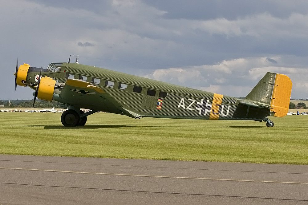
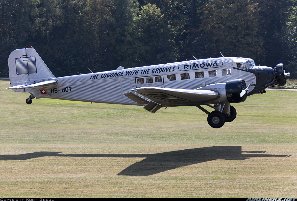
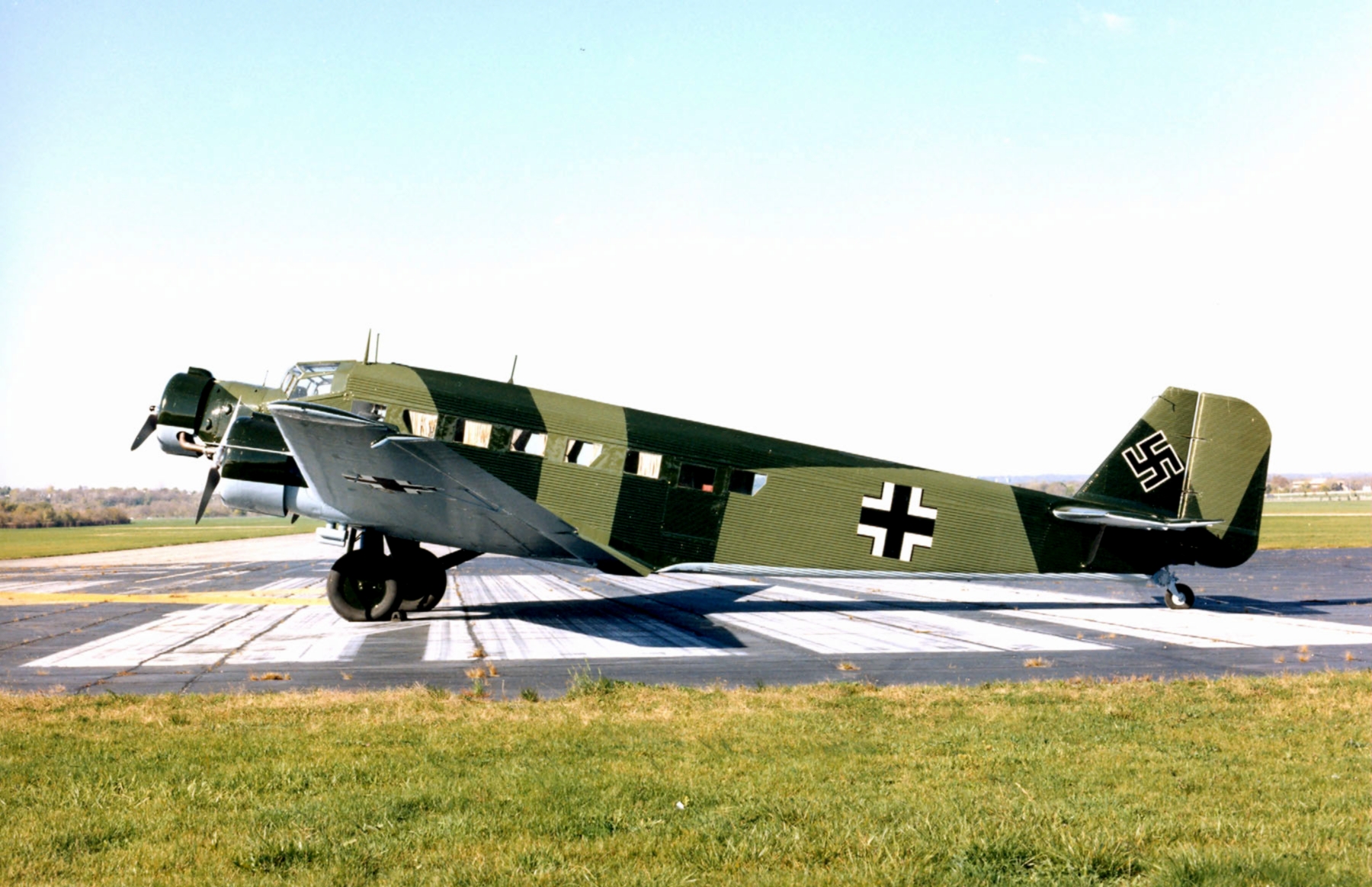
The Junkers Ju-52/3m (nicknamed Tante Ju (“Aunt Ju”) and Iron Annie) is a transport aircraft that was designed and manufactured by German aviation company Junkers. First introduced in 1930 the Junkers Ju-52 originally started out as a commercial endeavor and ended up being the workhorse of the Luftwaffe during WW-II. The Ju-52 entered service in the Luftwaffe as a make-shift bomber in 1935, however, its primary function during WW-II was as a troop and transport throughout Europe, Russia, and North Africa. Toward the end of the war the Ju-52's main function was that of a flying ambulance. Many Ju-52's saw service after the war as passenger aircraft, military transports and military trainers. As a general workhorse, the Ju-52 was invaluable: it was cheap and simple, easy to maintain in the field, could fly on only two of its three engines, had the ability to withstand crash landings with reasonable safety and could take serious damage. It had good STOL performance, robust construction, and interchangeable wheel/ski/float landing gear.
Development of the Ju-52 commenced in the late 1920s, headed by German aeronautical engineer Ernst Zindel. The aircraft's design incorporated a corrugated duralumin metal skin as a strengthening measure, which was a material design pioneered by Junkers and used on many of their aircraft, including the popular Junkers F13 1920s, the record-setting Junkers W33, and Junkers W34. The corrugation was a strength and weakness; it created strength but also higher aerodynamic drag; more importantly it allowed the practical use of aluminum before newer alloys were developed. In all, the Germans alone produced almost 5,000 Ju-52's during WW-II. After the war, the Amiot aircraft company produced another 400 for the French army to serve in the Indochina war; Spanish CASA even kept the plane in production since it was used as a multi-role transport by the Spanish air force until 1975. Today, only about 10 Ju-52's are still flying.
A New Generation — In April 2022, 90 years after the first flight of the Ju-52/3m, the Swiss Junkers Flugzeugwerke AG announced the successor model of the Ju-52, the Ju-52 New Generation. The Ju-52 New Generation will be able to carry 14 passengers and will have modern RED A03 engines and modern avionics. The market launch is not expected before 2025.
- Actual Aircraft Specifications (Junkers Ju-52/3m g3e):
- Crew: Two
- Capacity: 17 passengers
- Length: 19 m (62 ft)
- Wingspan: 29 m (96 ft)
- Height: 5.5 m (18.2 ft)
- Wing area: 110.50 m2 (1,189.4 sq ft)
- Empty weight: 5,720 kg (12,610 lb)
- Gross weight: 9,500 kg (20,944 lb)
- Max takeoff weight: 10,499 kg (23,146 lb)
- Power plant: 3 – BMW 132A-3 9-cylinder air-cooled radial piston engines, 541 kW (725 hp) each
- Propellers: 2-bladed variable-pitch propeller
- Maximum speed: 265.5 km/h (165.0 mph, 143.4 kn) at sea level 276.8 km/h (172.0 mph; 149.5 kn) at 910 m (3,000 ft)
- Cruise speed: 246 km/h (153 mph, 133 kn) maximum continuous at 910 m (3,000 ft) 209 km/h (130 mph; 113 kn) economical cruise
- Range: 998 km (620 mi, 539 nmi)
- Service ceiling: 5,900 m (19,360 ft)
- Wing loading: 83.35 kg/m2 (17.07 lb/sq ft)
- Armament: 1 – 7.92 mm (0.312 in) MG 15 machine gun or 13 mm (0.51 in) MG 131 machine gun in a dorsal position
- 1 – 7.92 mm (0.312 in) MG 15 machine gun in a semi-retractable dustbin turret
- Bombs: up to 500 kg (1,100 lb) of bombs
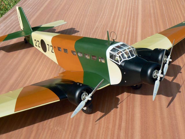
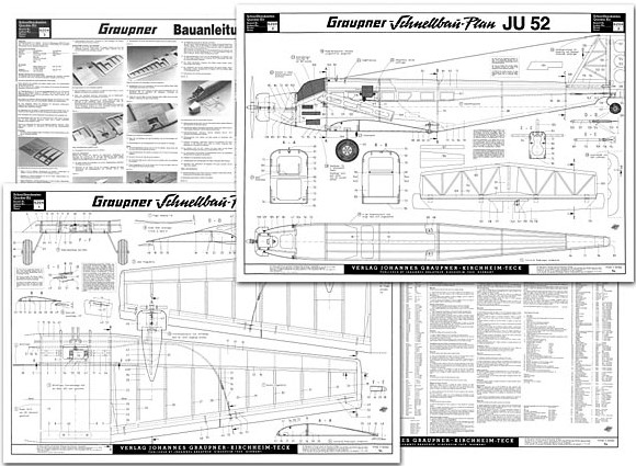
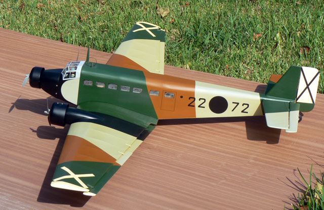

Images Source: Outerzone Junkers Ju-52 Webpage.
RC MODEL CONSTRUCTION: I must first caution that this build is NOT for someone just starting out in scratch building RC models. Graupner's 1/20 semi-scale Ju-52 was designed to be flown with three Speed 400 electric motors. A couple of changes that you may want to consider. You can use three small Hacker A20-16M outrunners or similar (the kit originally had speed 400's). Also use a 4-cell LiPo battery (the kit originally used an 7-cell sub-C NiCd pack). The three motors combined only pull 20 amps, so a 2,700mah pack will fly the model for longer than needed. Shortly cropped grass runways should not present a problem for the model. On a paved runway the Ju-52 lifts of in about 20-25 feet. You should also add washout to the wings as they are of a fairly steep taper. And of course aileron servos in the wings.
The wing is a conventional D-tube structure with spruce spars, cap strips and shear webs. Since the plans are from the Graupner kit and do not contain all rib profiles, you will need to use the one provided and then scale down for each of the other ribs in the wing. The scale ailerons hang below the wing and are actuated by a single servo via flexible cable push rods built into the wing. Each wing motor mounts to a plywood keel and is then covered with the plastic engine nacelle's. Take care to trim the nacelle's to get an exact fit to the wing profile; if you just follow the cutting line on the plastic you will probably end up with some small gaps between the nacelle and the wing. The simple wire landing gear is mounted by straps to a hardwood block in the wing.
The fully sheeted fuselage has flat sides and bottom with a curved top. Applying the top sheeting over the bulkheads and stringers can be made much easier if you first soak the sheeting in an ammonia/water solution to make it pliable, then pin it to the structure until dry, after which it can be easily glued in place. A clever design feature of the fuselage is that the battery tray is positioned behind the windshield so that the batteries can be removed for charging without taking off the wing. Simply remove the windshield and the batteries can be accessed through the opening in the front of the fuselage. The tail surfaces are built-up structures that are very light, yet quite stiff. The elevator and are sheet surfaces with the latter having three large lightening holes to reduce weight. The tail wheel wire mounts directly to the bottom of the rudder for steering.
The best part of flying the Ju-52 is the sound. Yes, I know, electrics are quiet, but if there are no engine models flying you can still hear the three props signing their beautiful synchronized song. And, unlike a gas model, there is no chance of an engine-out as all three electric motors work as one. Multi-engine flying without the engine-out landings, balky engines, trying to synchronize engines that don't want to run at the same rpm, and worrying if one engine will run out of fuel before the other — what more could you ask? When the juice does start to run down, all three motors stay in sync and set up for an uneventful final approach. Why would anyone want to fly a multi with anything but electric power?
- Model Specifications:
- Aircraft Type: 1/20th Semi-Scale Warbird
- Wing Span: 59″
- Total Wing Area: 403 square inches
- Fuselage Length: 39″
- Number of Channels: 4 - Ailerons, Rudder, Elevator, and Throttle
- Weight: approx. 56 oz.
- Wing Loading: 20.7 oz./square foot
- Glow Fuel Engines: N/A
- Electric Powered: Output of 200 watts each, 40 amp ESC, 4-cell 45C LiPo pack of 2,700mah.
The Graupner's Ju-52 RC model in this months edition can be built from a set of plans and articles from: “Outerzone.”
Outerzone Junkers Ju-52 Webpage.
AeroFred Graupner's Junkers Ju-52 Webpage.
Want to try building a larger sized Junkers Ju-52? Then click on this next link at Outerzone for a 84″ span Junkers Ju-52, sized for three 0.20 two-stroke glow engines. Junkers Ju-52 (oz5874).
I hope you have enjoyed this months selection, and just maybe, I have spurred some interest in trying your hand at building an RC model airplane.
Until next month - Keep the Balsa Dust Flying!!
Build of the Month Series - September 2024 Edition
I hope you enjoyed last months BOTM edition on the Das Ugly Stik model. If you have an RC model that you would like to see featured in this section or feel others may find interesting, please let me know and I will make every attempt to find scratch build plans, photos, and maybe even a published build article, which will then post in a future edition. Just send me an email @: Build of the Month.
Ok, now lets see what I have for the month of September 2024. As I have stated in earlier editions, I tend to favor Vintage or Old-timer RC model airplanes. Keeping the build simple, resulting in an RC model airplane that is gentle and easy to fly are key factors for someone new to scratch build and learning to fly. And how about something that is a large size to make it easier to see at altitude. So given these requirements, this edition features the Playboy Senior, a well known RC model airplane designed by Joe Elgin.

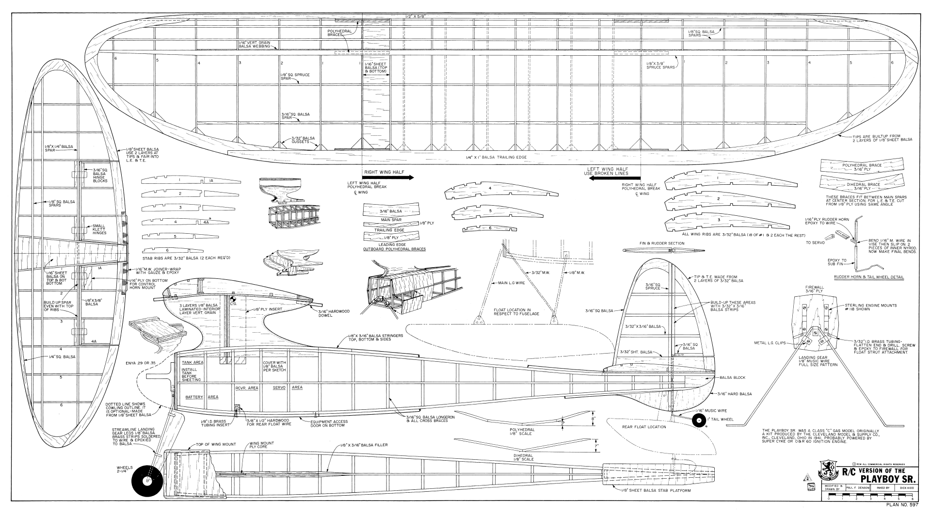
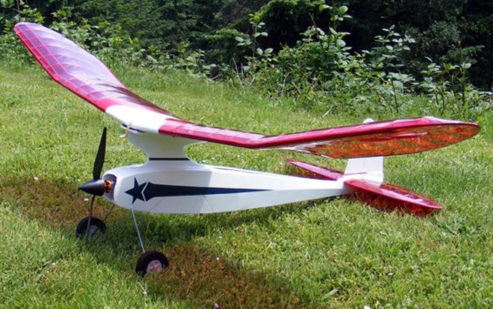
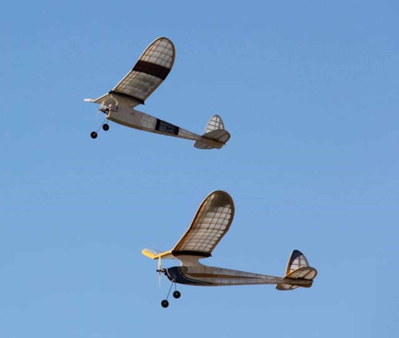
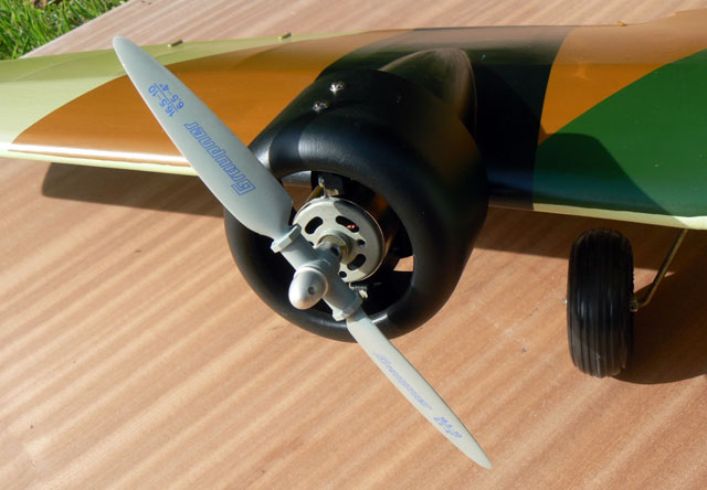
Images Source: Outerzone Playboy Senior Webpage.
The Playboy Senior is one of the best performing early pylon designs. Originally designed in 1938 by Joe Elgin, the Playboy Senior still has excellent performance in the initial high climb rate and then having a lovely glide and the ability to make the most of any thermal lift that may be about. The Playboy Senior first appeared as a Cleveland kit in 1939. See their site at Cleveland Air Line for more details. Presented in this months edition, is a later version modified by Paul Denson and printed in RCM May 1975.
Today eight-five years later, the name “Playboy” almost seems up-to-date. From years of experience in Free Flight, indoor and outdoor rubber, a small Free Flight gas job evolved. As gassies went in those days it was relatively small, “junior size” I guess you would call it, but extremely successful as a flyer. It performed! When it was scaled up to 7 ft wingspan, kitted and christened with the, then ridiculous name “Playboy” it became a powered sailplane - a real floater. Flown with an O&R .60 up front it started a new page in the history of RC modeling. In the winter of 1939, the kit hit the market and Bill Schwab built the first Playboy Senior. He went on to win many contests, first in Cleveland, first in Akron, and sixth in the Chicago NATS. This is the plane that broke the world's record twice within 7 days. That was just the start, and she is still going strong today.
As an R/C trainer, the Playboy Senior has no peer. No matter what position you might get it into, just let go of both controls and she will get herself out of trouble. It is too inherently stable to stay in any position but right-side-up. Don't try to fly it inverted - it can get into that position but, since the airfoil is designed for lift, when inverted it lifts down and fast. It would decidedly be a way to get out of a boomer thermal, quickly.
RC Model Construction: The plans for the Playboy are pretty much self-explanatory, but perhaps a few words are in order - particularly having to do with the modification for R/C. Extremely important is the beefing up of the wing to stand the stresses placed upon it by movable control surfaces, after all, you are going to be tempted to do an occasional loop or snap roll, and the wing must be strong enough to take it. Even though the spars are spruce, and you have 1/8″ ply sheet dihedral braces, the main spars must be webbed with 1/16″ sheet vertical grained balsa out at least to the polyhedral break. For those who had not webbed the prototype, they snapped the wing just outboard of the dihedral brace pulling out of a dive before going into a loop. The bottom spar broke the glue joint between it and the dihedral brace and the top spar failed. If it had been webbed this would not have happened. Because of the pylon on top, entrance to the flight pack must be through the bottom. Finish the cross-grain planking on the front of the fuselage then remove the section designated as the equipment access door.
Don't forget to build the fuel tank area before planking the fuselage. The fuel tank may be removed through the access door, if necessary. Use the largest cylindrical fuel tank that will fit the space, in this case a 6-ounce tank. A .29 will run for about 15-20 minutes at half throttle on this much fuel. Make sure the 3/16″ square spruce vertical piece of the fin extends through the sub fin. Since it passes through the stab it will weld the tail assembly into a compact unit. Furthermore, if you decide to use floats it will be the hardwood point of attachment for the rear float. If there is even a small chance that you intend to fly the Playboy Sr on floats, install the 3/8x1/2″ in hardwood cross member in the fuselage before planking - it may be added later on but is difficult to do so.
- Model Specifications:
- Wing Span: 80″
- Wing Chord: 10.75″
- Total Wing Area: 750 square inches
- Horizontal Stab Span: 27.625″
- Horizontal Stab Area: 175 square inches
- Fuselage Length: 40.75″
- Number of Channels: 3 - rudder, elevator, and throttle
- Weight: approx. 48 oz. with glow engine
- Wing Loading: 9.23 oz./square foot
- Glow Fuel Engines: 0.29 - 0.35 two-stroke
- Electric Powered: Output of 600 - 700 Watts, 60 amp ESC, 4 cell 45C LiPo pack of 4000mah.
Here is a link to an excellent build log: “Playboy Senior Build”. This build log has lots of great images that will take you step-by-step through the construction of the Playboy Senior. The finished model is powered by a OS 0.26 four-stroke with a 10x6 prop. The build is a 3-channel RC, elevator, rudder and throttle. A very well done build log. The model in the build log is built from a great set of plans and article which are available from: “Outerzone”
Outerzone Playboy Senior Webpage.
Want to try building the Playboy Senior but not as a scratch build? Then click on this next link for a 80″ span Playboy Senior from Hanger One Kits, sized for 0.35 to 0.60 two-stroke glow engines. Their laser cut kit will give you many enjoyable hours of building and flying. Stable enough to be a relaxing Sunday flyer, and it's under-cambered airfoil making it a great performer in thermals. Playboy Senior 80". Another source for a Playboy Senior short kit is available from Ben Buckle Vintage Kits at this next link: Playboy Senior. Their Playboy Senior short kit includes pre-cut wing ribs, tip shapes and formers, balsa strip, sheet and block parts, undercarriage wire, hardwoods, a hardware pack and full-size plans. Everything needed to build the basic airframe of the model.


I hope you have enjoyed this months selection, and just maybe, I have spurred some interest in trying your hand at building an RC model airplane.
Until next month - Keep the Balsa Dust Flying!!
Build of the Month Series - August 2024 Edition
I hope you enjoyed last months BOTM edition on the SIG RC-70 Tri-star model. If you have an RC model that you would like to see featured in this section or feel others may find interesting, please let me know and I will make every attempt to find scratch build plans, photos, and maybe even a published build article, which will then post in a future edition. Just send me an email @: Build of the Month.
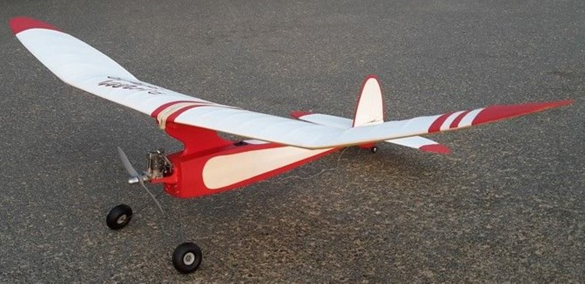
Ok, now lets see what I have for the month of August 2024. With the main objective of my BOTM Series being to help newcomers to the hobby, I feel this months RC model should support that objective. We want a Balsa RC sport plane that will be simple to build and fly, can be built as electric or glow powered, and will not require all kinds of special tools to build. So given these requirements, this month features the Das Ugly Stik, a well known RC model designed by Phil Kraft.


Images Source: Outerzone Das Ugly Stik Webpage.
For decades Phil Kraft’s Das Ugly Stik has been the standard by which sport planes are measured. It is common knowledge that the original Das Ugly Stik has been copied dozens of times by various designers and kit manufacturers, resulting in sweet sticks, sweet and low sticks, giant sticks, lite sticks, micro sticks and bipe sticks. Some sport planes have been designed by starting with the moments, incidence's, and areas of the Das Ugly Stik and making the shapes of the tail, wing tips and fuselage prettier. This is a safe strategy, because such a plane would still fly pretty much like an Ugly Stik even if it is not ugly.
A less well known fact is that this sort of mimicry is how Phil Kraft designed the Das Ugly Stik in the first place. In 1964 RC Modeler magazine published a design by Don Mathes called the Digester. Mathes needed a test plane for his new digital radio. The name Digester was short hand for Digital Radio Tester. It's a big plane with a big wing and three channels. Looking at the airfoil and general layout of the Digester, it's easy to conclude that Phil Kraft took it as inspiration, simplified the nose and tail, added ailerons, and scalloped the trailing edges for chuckles. Phil did something right. Although the Digester is mostly forgotten, the Stik is the most successful design in RC history.
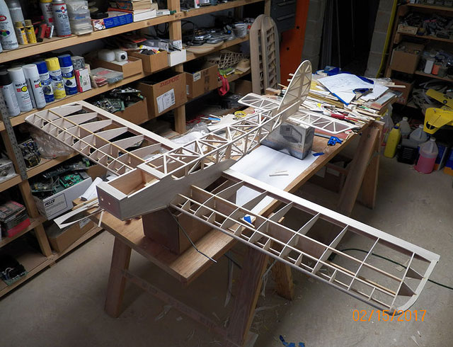
The Ugly Stik fits the requirements perfectly as a trainer. It is about as simple as possible to construct. It is rugged and very easy to fly. Flying of the Ugly Stik is equally as simple as the construction. The design is not overly critical to the Center of Gravity location and should balance approximately on the main spar. No thrust offsets are used. To sum it up, considering the minimum amount of time and effort put into construction, I doubt that you will ever have more fun flying a radio controlled model aircraft. I believe it is an excellent choice for the beginner and an ideal trainer for multi proportional flying. I hope you enjoy it!
- Model Specifications:
- Wing Span: 60″
- Wing Chord: 12.5″
- Total Wing Area: 720 square inches
- Horizontal Stab Span: 22″
- Horizontal Stab Area: 160 square inches
- Fuselage Length: 46″
- Number of Channels: 4 - ailerons, elevator, rudder and throttle
- Weight: approx. 96 oz. with glow engine
- Wing Loading: 18 oz./square foot
- Glow Fuel Engines: 0.40 - 0.61 two-stroke
- Electric Powered: Output of 800-1,200 Watts, 60-85 amp ESC, 4-6 cell 45C LiPo pack of 5000mah.
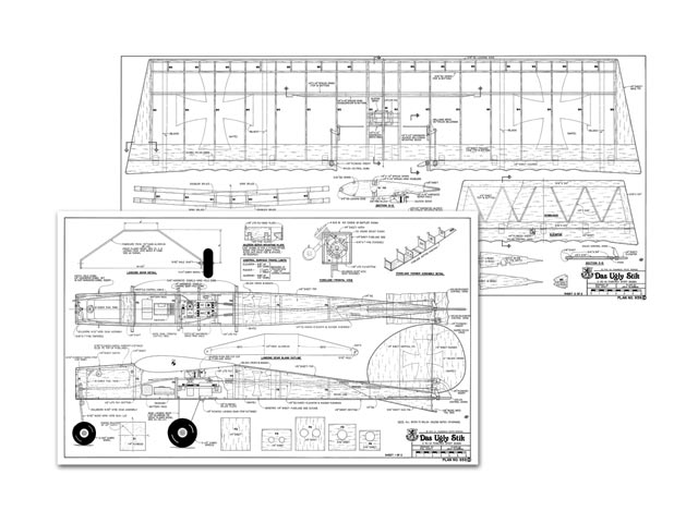
Here is a link to an excellent build series video: “Das Ugly Stik Balsa RC Aeroplane Build by Mark Robinson”. This is a 13-part build series that will take you step-by-step through the construction of the Das Ugly Stik, culminating in a maiden flight, and followed by a build and flight review. The finished model is powered by a 0.61 Tiger Pro 2-stroke nitro engine. The build is a 4-channel RC, ailerons, elevator, rudder and throttle. A very well done video series.The model in the video is built from a great set of plans and articles which are available from: “Outerzone.”
Outerzone Das Ugly Stik Webpage.
Want to try building the Das Ugly Stik but want something a little smaller? Then click on this next link to AeroFred.com for a 46″ span Das Little Stik, sized for 0.20 to 0.35 2-stroke glow engines. All the Stiks have well-deserved reputations as being easy to build, great sport aerobatic aircraft and aileron trainers, and having tough airframes. The landing gear configuration can be a traditional tail dragger or a tricycle landing gear, both having advantages and disadvantages for the novice flyer. There is sufficient detail on the plans to readily allow even novice builders to build this "mid-size" Stik! Das Liddle Stik.
I hope you have enjoyed this months selection, and just maybe, I have spurred some interest in trying your hand at building an RC model airplane.
Until next month - Keep the Balsa Dust Flying!!
 All HTML & CSS Coded by Larry